Author:
Sven Jimenez Rodriguez, Product Sales Manager Capacitors, and Christian Kasper, Technical Support, Rutronik
Date
05/02/2022
 PDF
PDF

Click image to enlarge
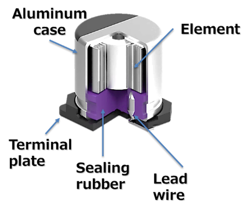
Figure 1: An electrolytic capacitor essentially consists of an anode and cathode film, separator paper, and electrolytes
Electrolytic and polymer hybrid capacitors have an almost identical design: they consist of a cathode side and an anode side, which in turn are both made of aluminum film. The film for the anode is subjected to an oxidation process, which creates an aluminum oxide layer forming the dielectric. Both films are rolled up with separator paper to form a winding element (Fig.1, Fig.2).
Click image to enlarge
Figure 2: Basic design of electrolytic and polymer capacitors
The difference between the two types of capacitor is the material used for the filling process, which also gives them their name: electrolytic capacitors are filled with electrolytes, while polymer hybrid capacitors utilize either polymerized electrolyte or a combination of solid and liquid polymer.
Both types boast a number of advantages, such as high capacitance values despite their small size, low costs, and availability in various designs, e.g. SMD, THT, or snap-in.
Compared to electrolytic capacitors, polymer hybrid capacitors additionally provide a higher ripple current capacity as well as lower internal resistance at low temperatures and more stable capacitance at high frequencies.
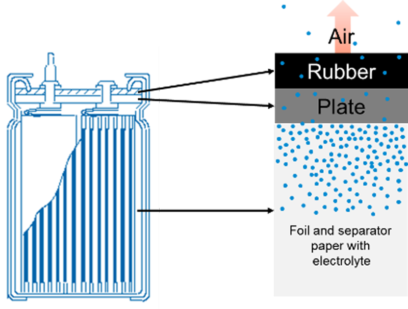
The shortcoming of both technologies lies in their limited lifetime. During operation, the electrolyte or the liquid polymer shrinks (Fig. 3).
Click image to enlarge
Figure 3: The electrolyte or liquid polymer diffuses during operation, resulting in a limited capacitor lifetime.
The Arrhenius equation provides a rough estimate of a capacitor lifetime
What limits the lifetime
The biggest factor affecting the lifetime of electrolytic and polymer hybrid capacitors is the core temperature of the capacitor. It increases as the ambient temperature and the level of applied ripple current increase. Further, mechanical stress due to excessive ripple current can also damage the oxide layer and cause additional consumption of electrolyte due to self-healing. Self-healing is the ability of electrolytic and polymer hybrid capacitors to restore the oxide layer by means of a chemical reaction between the electrolyte and the aluminum. Electrolyte shrinkage also causes the electrical parameters to deteriorate, for example the capacitance as well as the equivalent series resistance (ESR) and the loss factor.
End of life usually refers to the phase when the data sheet parameters – generally capacitance loss and increase in loss factor percentage – are undershot.
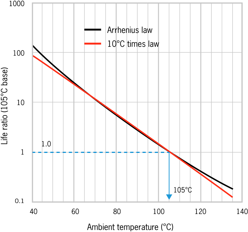
When selecting a capacitor that does not undershoot the electrical parameters during the targeted operating period of the end product, the Arrhenius equation can be used to make an initial assessment. As shown in Figure 4, lifetime as a function of the diffusion coefficient resembles the Arrhenius equation to a large extent. Therefore, as a rule of thumb, the following statement can also be made: a 50°F (10oC) reduction in the operating temperature doubles the lifetime.
Click image to enlarge
Figure 4: The Arrhenius equation and the rule of thumb that states the capacitor lifetime doubles with every 50°F (10 C) reduction in the operating temperature offer almost the same results
The Arrhenius equation provides only a rough guide value, as it fails to take into account the significant impact of the ripple current on self-heating.
Support from capacitor suppliers
To obtain an accurate lifetime calculation, working with the respective capacitor supplier is recommended. This calculation requires a mission profile from the customer. It details the number of actual operating hours in the relevant temperature range.
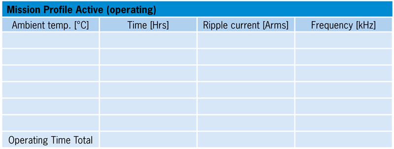
Click image to enlarge
Figure 5: The example of a mission profile shows which parameters the supplier needs for accurate lifetime calculation
Each supplier uses individual calculations for their own products that incorporate the temperature profile and ripple current load. As such, the supplier can perform a detailed lifetime calculation using the mission profile provided by the customer.
Using the mission profile, the supplier can evaluate and recommend the capacitor for the corresponding application. This also prevents use of an over-specified – and thus more expensive – capacitor.
Cooling ensures a longer lifetime
Heat sinks that increase the surface area are a good way to improve heat dissipation and thus increase the capacitor lifetime. Active cooling through the use of fans or water, for example, can ensure even better heat dissipation. Such cooling concepts can also be taken into account when validating the component and calculated into the lifetime calculation.
The connection of the cooling elements to the capacitor also plays a key role.
Attaching the cooling element directly to the component is often more effective than placing it directly on the opposite side of the board. Moreover, it is important to also consider the peripheral units of the capacitor, as it both radiates and absorbs heat through its legs. This is especially true if power semiconductors or other heat-generating components are in the vicinity. This heat input can also be included in the lifetime calculation if empirical data, e.g. on temperature, current, voltage, and frequency, is available.
If you use a thermal paste or thermal pads, their thermal resistance is decisive. The lower it is, the more efficient the heat dissipation. If the cooling element needs to be electrically isolated, an insulating thermal paste or suitable pads should be selected.
The thermal resistance model, from the core (winding element) to the legs and the package of the capacitor, can be obtained by customers from the supplier if they wish to perform a calculation or simulation themselves.
If both the heat situation and the thermal resistances from the cap or PCB to the cooling element are fully known, the additional heat dissipation or supply can be inferred. Once possible heat dissipation has been verified, the supplier may allow a higher ripple current for the layout – but only if the maximum ripple current specified by the supplier is not exceeded, since that would result in a mechanical load on the capacitor.
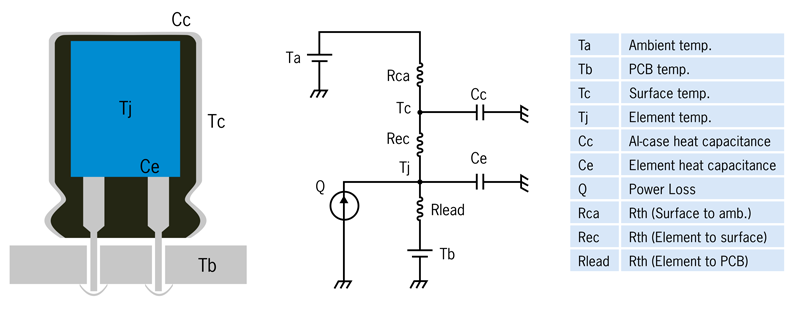
Click image to enlarge
Figure 6: Thermal equivalent circuit diagram of the capacitor
Conclusion
The Arrhenius equation is recommended to determine an initial guide value when selecting a capacitor. Using a mission profile, the lifetime of the selected capacitor in the application can be calculated exactly. This also takes into account the level of self-heating caused by the ripple current. To maximize the capacitor lifetime, it is worth looking at possible cooling concepts and involving the supplier or distributor in the development process.