Use Soft Termination to Improve Reliability in Vehicle Applications
Soft termination improves connection reliability by limiting the effects of stress caused by temperature and flexure, particularly important as EVs become more prominent
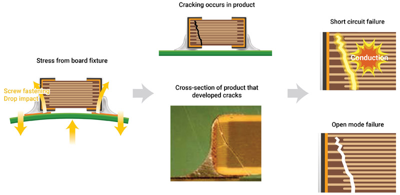
Figure 1: Shows major causes and the process of board flexure
The automotive industry is in the midst of a transition from internal combustion engines (ICE) to electric vehicles (EV). At the same time, automakers are adding assisted-driving features to both ICE vehicles and EVs. Both trends represent multifunctional capabilities enabled by high power electronic control units (ECUs).
A practical result of both trends is that automakers are compelled to move ECUs from protected locations inside their vehicles to areas where they are subject to environmental stresses. Subjecting ECUs to extreme heat, humidity, and other harsh conditions is a potential problem, but it’s a problem with a solution: using soft termination.
ADAS and EVs
Advanced driver assistance systems (ADAS) features are becoming standard features in cars. Some ADAS features, such as automatic parking, are conveniences, but most are safety features. Common examples include automatic emergency braking and blind spot collision warning. ADAS safety features are understandably subject to stringent government regulations.
Federal and state programs adopted in recent years to reduce emissions of CO2 jump-started the transition from traditional fossil fuels to electric powertrains. Fully electric cars and partially electric hybrids are gradually gaining market share. EVs represented 5 percent of all cars sold worldwide in 2020, 9 percent in 2021, and 14 percent in 2022, according to the International Energy Agency. Global unit sales exceeded 10 million vehicles in 2022, and the market is on track to sell 14 million in 2023.
Safety standards and soft termination
EVs and ADAS features represent multifunctional capabilities. For example, high power ECUs support image processing for ADAS, whereas low power ECUs are ideal for sensor and body applications. These capabilities must be implemented in real time, otherwise they are useless. That makes it paramount to reduce signal latency, which means moving the ECUs closer to the sensors, and as a practical matter that places them in environmentally challenging locations such as the engine compartment.
The prevailing functional safety standard for automotive electronic equipment is ISO 26262. Reliability is a critical factor in meeting thisstandard. ADAS applications incorporate passive components that must be durable. They must have the mechanical strength to withstand rapid temperature cycles. The components subject to these considerations include multilayer ceramic chip capacitors (MLCCs), inductors for decoupling and power supply circuitry, and chip beads for signal and power supply lines.
A key tactic for supporting durability requirements is to attach components with resin electrodes (soft termination), which addresses the two common failure mechanisms: flex cracks and solder cracks.
Flex cracks
Flex cracking is due to excessive circuit board bending or flexing – flexure. Cracking is a potential problem from the outset; it can occur during the manufacturing process, in response to solder stress due to an inappropriate amount of solder, or when stress is applied at the time of de-paneling or screw fastening. It can also occur during final assembly, and of course it can happen during use, where exposure to continuous vibration occurs.
MLCCs and ferrite components tend to be strong when under compression, but they can be weak in tension. This discrepancy is due, in part, to the nature of ceramics, which are often inherently brittle. Unlike metals, when ceramics are subjected to a tensile load, they are unable to yield and relieve the stress. This is why, when a soldered component experiences excessive board flex, a crack is a too-common result.
A flex crack can lead to the formation of an electrical conduction path between opposing internal electrodes. Continued voltage and temperature cycling can produce a flex crack that can propagate to a fail short condition. A short circuit could lead to a range of problems that include heat generation, smoking, or ignition.
Mitigating flex cracks
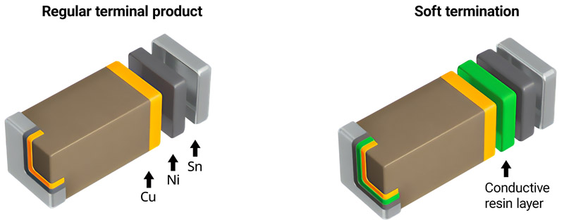
In a traditional MLCC, the copper (Cu) underlayer of the terminal electrode is electroplated with nickel (Ni) and tin (Sn). Soft termination is achieved by adding a conductive resin layer in between the copper and nickel layers. The resin reduces the stresses accompanying expansion or shrinkage of the solder joints due to thermal shock or flex stress on the board.
Click image to enlarge
Figure 2: The difference between a regular terminal product, and soft termination in MLCCs
In a pair of stress tests, one on a standard product and one on a soft termination product, the standard product experienced flexure cracks at about 4 mm of deflection. No cracking occurred, meanwhile, in the soft termination product, even with over 10 mm of bending stress applied. That extreme level of stress in the test resulted in peeling of the nickel layer and the conductive resin layer but, significantly, cracks in the ceramic body were prevented.
MLCCs with dual safety design provide the highest protection from cracking and short circuits. In the case of battery power lines, safety can be enhanced by replacing a traditional MLCC with one that features a dual fail-safe function.
In a dual fail-safe implementation, the conductive resin is layered in the terminal electrodes, which prevents cracks. The internal electrodes are structured to be functionally equivalent to a series-connection of two capacitors. This structure reduces the risk of short-circuiting, even if a crack does occur on the capacitor element.
Since just one serial-design MLCC can achieve AEC-Q200 compliant safety, this single part can take the place of two standard MLCCs connected in series. The parts count, PCB space, and mounting costs are cut in half.
The terminal electrode structure of traditional inductors and chip beads can be treated similarly. Here, the silver (Ag) underlayer is plated with Ni and Sn, and soft termination is achieved by applying a conductive resin layer between the plating layers.
In tests comparing multilayer inductors and chip beads with resin electrodes, parts that have soft termination have nearly twice the board flex resistance (critical bending) of products with conventional electrodes. In traditional products, cracks developed on the ceramic element with a flex of about 4 mm. In contrast, products with soft termination can withstand more than 7 mm of flex without cracking.

Click image to enlarge
Figure 3: Results from a comparison of the flex strengths of a regular terminal product and soft termination. Element cracks occurred in the regular product after it was flexed up to about 4 mm. In contrast, no cracking occurred with soft termination, even after it was flexed 10 mm
Thermal cracks in solder joints
Solder cracks occur mainly because of thermal fatigue due to temperature variations. The problem can be exacerbated by using lead-free solder, which is more brittle than lead-bearing solders. Caution is recommended when mounting passive components near sources of excessive heat where sudden temperature changes (thermal shock) can occur.
When subject to thermal stress, the mismatch in the coefficient of thermal expansion (CTE) of the solder in the passive component and PCB can cause solder cracks. This can also occur when temperature control is insufficient during the soldering process.
Click image to enlarge
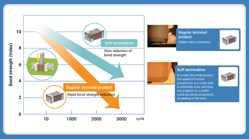
Figure 4: The comparison between normal terminal product and soft termination, illustrating the bond strength decrease rate
Soft termination mitigates thermal cracking
MLCCs with resin electrodes help to reduce thermal cracks in solder joints due to their outstanding thermal shock resistance. In a comparison test, standard termination products and resin electrode products were subjected to 3,000 thermal shock cycles from -55°C to +125°C. While the push strength of the conventional products decreased by approximately 90 percent, the soft termination MLCCs maintained 50 percent of their shear strength.
A 2,000-cycle thermal shock test data of inductors and chip beads (-55°C to 150°C) show that the anchoring strength of the conventional product declined approximately 50 percent, as compared to around 20 percent for the resin electrode.
Conclusions
Mechanical stresses can make passive components crack, which results in circuit failure. Meanwhile, solder cracking will occur when there is excessive stress between the board and the solder joint, causing an open circuit or the component to lose adhesion to the PCB.
Soft termination will always be a useful technique for mitigating if not entirely avoiding the problem.
Either way, it always helps to avoid placing components in locations that may experience significant post-solder handling stresses, such as near mounting screws, PCB edges and corners.
For the same reasons, attention should be paid to locations where extreme temperature changes (thermal cycling) occur, such as in an automobile's engine compartment. Due to the enhanced robustness of soft termination products, the effects of board flexure and thermal shock stresses can be suppressed, improving connection reliability.