
Practical and theoretical considerations
Choosing a UPS of the right capacity for a commercial or industrial application may appear as a simple task. In reality however, making the correct choice depends on knowledge and understanding of a site's load and its characteristics. This article looks at the practical and more theoretical considerations contributing to the process of defining the UPS sizing required. Although typically associated with data centres, Uninterruptible Power Supply (UPS) systems are finding their way into an ever-widening, diverse range of environments. This is due to the increasing number of telecoms, medical, industrial processing, retail and other applications that now rely critically on electrical equipment and power availability. This diversity imposes widely varying loads on any UPS chosen. Additionally, different applications generate different views on just how critical their load is, and the degree of protection that must be provided. Therefore, this article starts with some practical considerations for site load sizing, before addressing at how to provide for this load with a level of security appropriate to the application. Clearly the load at any given site will be unique, depending on the mix of equipment in its make-up. However the load will also be time-variant in several ways. There will be daily and weekly variations as office occupancy and equipment use drops overnight or during weekends and holidays, and seasonal variations as the weather, and demand on air-conditioning or heating, changes. Longer term changes arising from operational expansion and addition of new equipment are also likely. Investigation of the critical load's on site components, including measurement of the load's performance over a meaningful time, is a necessary part of the UPS sizing exercise. Within the UK, the UPS is usually fed from the National Grid electrical mains, and feeds the site's critical load. During a mains failure, the UPS batteries maintain supply. To start sizing the UPS, the load should be scoped in terms of its required supply voltage, frequency, number of phases, load current, power factor and power consumption. UPS manufacturers express their products' power capability in VA or kVA. Meanwhile, equipment power consumption may be expressed in Watts. If so, its contribution to the load in VA can be found by multiplying its load current by its supply voltage. Alternatively its power consumption in Watts can be divided by its stated Power Factor to reveal its VA load. Manufacturers frequently overstate their equipment consumption by 20% or so to ensure the installer provides an adequate supply; however this over-rating cannot be relied on, and if in doubt the load should be measured. This measurement activity can form part of the overall site survey. This should include installing portable measuring and monitoring equipment to record information about the load over a period of time. The period depends on the site situation; for example it would be misleading to monitor an office network over a weekend when very few staff have their PCs on. The nature as well as the size of the load should be considered. Although UPSs are generally resilient, certain load types do present challenges which must be allowed for. These include blade servers, fluorescent gas discharge lighting, motors and compressors, air conditioning equipment and laser printers. These can all draw high currents during normal operation, and even higher inrush currents during start-up. This may overload the UPS, causing a transfer to bypass. Blade servers also impact UPSs in another way. Unlike much equipment with a lagging power factor, blade servers present a leading power factor. As these servers are powerful and increasingly popular within computer installations, the critical load's overall power factor may become leading. This presents a major problem with legacy transformer based UPS systems. For example a 300 kVA UPS requires derating by 24% for a 0.9 leading power factor.� By contrast, a modern transformerless 300 kVA does not derate at 0.9 leading power factor.
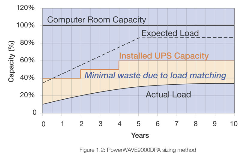
If a three-phase UPS is supplying a load with single-phase components, these components should be distributed as evenly as possible between the phases to allow the capacity of the UPS to be optimally utilized. A balanced load is also presented to the mains or, if installed, the generator if the UPS is bypassed. Although modern UPS systems can cope with phase imbalance, the load on any single phase must never exceed 33% of the total UPS loading.. When all the load information has been collected, measured and collated, the required UPS capacity will become apparent. It is normal practice to add contingency capacity of typically 20% to this value. Additionally it is essential to carefully consider the site's future expansion plans and allow for these in the UPS configuration accordingly. Most UPS manufacturers offer modular rackmounting UPS systems to allow scalability; A modular system's total output is the sum of all its component modules'. For such systems, the only initial requirement is to allow sufficient racking space, as more rackmounting UPS modules can easily be added when site expansion demands extra capacity. As mentioned at the start of this article, the load's criticality will also influence the final decisions on the UPS's size and configuration. A small minority of users will prefer the initial capital savings of a capacity system - that is, a system with enough capacity to fully support its load as long as none of its constituent components or modules fail. If a failure does occur, the only solution is to immediately transfer the load to bypass, where it will be fed from the raw mains supply. Consider, for example a load of 270 kVA supplied by three 100 kVA units configured in parallel. Under normal circumstances, each unit will be supplying about 90 kVA, but if one module fails the other two will be called upon to supply up to 135 kVA each. This will substantially overload them, invoking a switch to bypass.
In practice, most applications today demand a degree of resilience to failure from their UPS system. This means that the UPS should continue to fully support the load even if one or possibly more modules should fail. This redundant arrangement is more precisely known as an N+1 redundant system. �N' represents the number of modules required to fully support the load, and �1' is for the single redundant module. If the application warrants it, more than one redundant module can be supplied to create an N+n redundant configuration. �n' is the coefficient of redundancy. These guidelines allow users or design consultants to specify a UPS capacity which allows for the conditions prevailing on the user's site together with considerations of the resilience to failure required. This decision can then be added to other selection criteria including the UPS's efficiency and running costs, its topology, its upgradeability, its size and weight, its flexibility of battery configuration and battery autonomy and its serviceability. Further issues such as cost, the reputation of the UPS supplier and the availability of references for existing installations are important as well. Any reputable UPS supplier will be able to help with site surveys, discuss the criticality of the load and other factors, and advise on UPS configuration and sizing accordingly. www.upspower.co.uk


