Author:
Len Crane, Senior Technologist, Coilcraft
Date
04/29/2025
 PDF
PDF

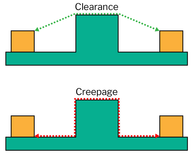
Figure 1: Clearance is the line-of-sight distance between conductors in space
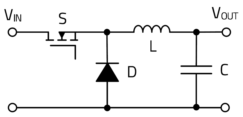
New power electronic developments are bringing the hazards of electrical energy closer to users than ever before. There are developing applications like electrified vehicles with 400 v or 800 v batteries, data centers with +/- 400 v racks, and faster switching devices with 650 v or higher ratings. These innovations drive the increased use of hazardous voltages into new application areas and environments.
You might ask whether transformer designers already know how to design for IEC and UL standard requirements, and the answer is yes, of course. However, there often seems to be important information missing from too many important design conversations, because designing isolating transformers to properly meet published safety standards from IEC, UL and the like requires a detailed understanding of how a transformer will be used in the application and on a variety of expected environmental conditions. That’s information the transformer designer won’t have without good and complete communication from the customer/application designer, and to have the best communication, they must speak the common language of the safety standards. Over-designing a transformer for safety requirements runs the very real risk of a design that is larger, more expensive, and lower performance than it needs to be. Even worse, under-designing for insulation requirements creates the real possibility of electronic devices that present real user hazards. Many designers are familiar with creepage and clearance distances, but meeting those requirements must take into account many factors. It isn’t really difficult, but can be confusing to those not familiar, and where safety is concerned, there should be no room allowed for mistakes. This article intends to clarify the important concepts for all designers to consider.
Safety Standards
This article provides education on the general concepts of safety insulation as per published international safety standards. It is not intended to provide exact requirements per any specific published standard. Always confirm your designs with your safety expert or directly with the appropriate safety agency.
This article refers to safety standards such as IEC 61558-1 ed.3.0 “Copyright © 2018 IEC Geneva, Switzerland. www.iec.ch” Safety of transformers, reactors, power supply units and combinations thereof and IEC 62368-1 ed.3.0 “Copyright © 2018 IEC Geneva, Switzerland. www.iec.ch” Audio/video, information and communication technology equipment
Creepage and Clearance
Creepage and clearance are some of the most commonly used terms, hence a good starting point. As a transformer company, we might hear for example that “my transformer must have 10 mm creepage distance.” That may well be true, but that statement alone is critically incomplete for the designer. Creepage distance requirements ALWAYS depend on the insulating material used, so unless the creepage requirement is conveyed along with the exact transformer build information, it really has no practical meaning in the context of safety standard requirements. To understand, we start with the real meaning of these terms.
Clearance distance, as shown in figure 1, is the shortest straight-line distance between two conductors. This is a very straightforward concept, but the amount of clearance spacing needed for any given applications depends not just on the voltage difference to be isolated, but also must consider the air between the conductors and whether the air in the specific application is likely to include significant dirt/dust or humidity.
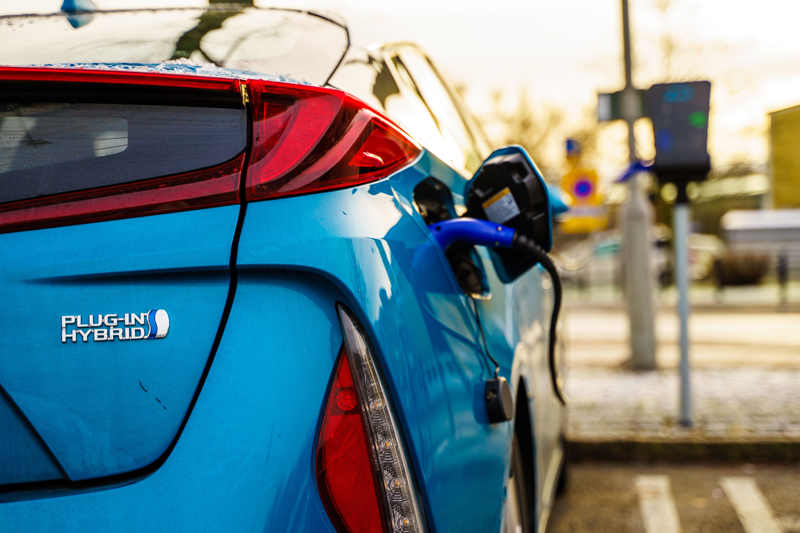
Creepage distance addresses the situation in which the conductors to be isolated are not in space, but rather have an insulating surface in common, which of course is the typical situation inside a transformer or on a pcb surface. Figure 2 (a) shows two conductors connected to a green insulating surface which could represent a pcb or transformer bobbin. The creepage distance is measured along that green insulating surface. In this simple case clearance = creepage distance. However, that’s not always true since they represent similar but different quantities. For example, Figures 2 (b) and (c) show the differences when the conductors are not at right angles to the insulation surface. Figure 2 (b) shows the conductors angled toward each other. This leaves the creepage spacing unchanged along the surface but has the effect of reducing the clearance spacing as the “in air” ends get closer. In this case clearance < creepage. Figure 2 (c) has a slightly surprising effect, which is not quite the opposite of 2 (b). Again the creepage appears unchanged but the clearance is not increased, so clearance = creepage once again. Where creepage is the shortest distance along a surface, clearance is the shortest line-of-sight distance regardless of whether that occurs across a surface or not.
Click image to enlarge
Figure 2: Clearance & Creepage Differences
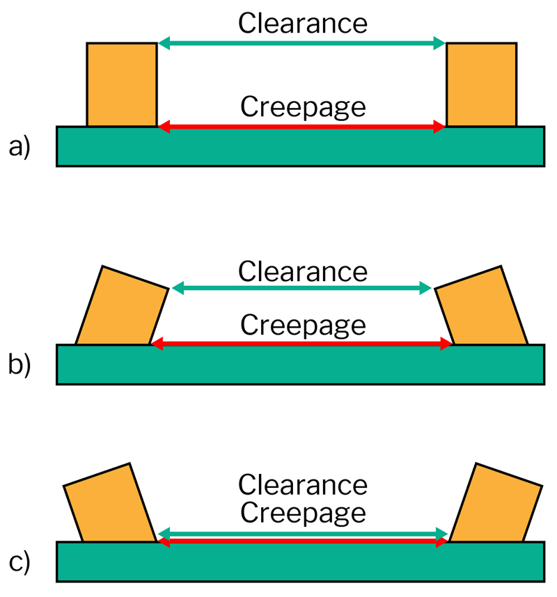
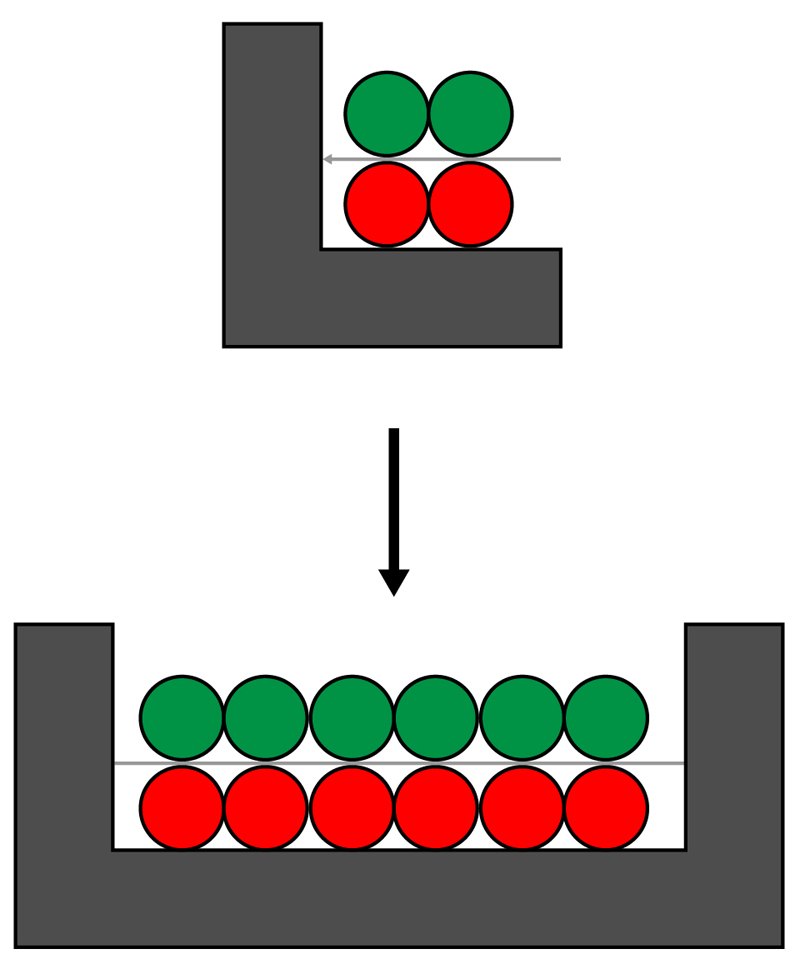
The goal for designing the safest transformer is to achieve the smallest possible transformer size while providing the maximum effective creepage and clearance spacings within that small transformer size. Figure 3 shows that adding a detailed shape to the transformer bobbin increases both creepage and clearance distance without necessarily increasing transformer size.
Click image to enlarge
Figure 3: Clearance and Creepage Increased by Shaping the Insulation
Distance Through Insulation
To create an effective transformer with good coupling between windings, it is desirable to have those windings in close proximity and most cases in direct contact with other windings. To maintain voltage isolation between windings, it is most common to place thin insulating tape between them. The requirements for such insulating tape layers are defined in safety standards as “distance through insulation”. Figure 4 shows a common challenge in insulating this way. The tape insulation can be perfectly suitable between windings but a challenge comes at the ends of the windings, where there is little to no creepage or clearance spacing between the end turn of one winding to the end turn of the other winding. In order to provide clearance and creepage between windings, some way must be found to extend the insulation beyond the ends of the windings. If this is not done cleverly, it can have the unfortunate result of wasting space and causing the transformer to be less efficient.
Click image to enlarge
Figure 4: Providing Clearance and Creepage Between Transformer Windings
What Determines How Much Clearance and Creepage are Required for a Specific Design?
Now we come to this important question and why it’s so important to discuss at the beginning of any project requiring an isolation transformer. Clearance and creepage as discussed above are seen to be relatively simple concepts, yet determining the spacings for any project requires good communication. Many factors need to be considered and all of them are defined in the safety standards themselves. They must be looked up in the appropriate standards table when determining the required clearance and creepage spacing.
Insulation Class
This might be one of the most confusing considerations, because the answer lies in the application. Determining the required insulation class depends on the type of circuits to which the transformer is connected. In the most general terms, the most crucial thing is protecting users from coming in contact with hazardous voltage, so of course the highest class of insulation is generally required between hazardous voltage and user-touchable circuits. A higher level of insulation is generally required then, between primary and secondary transformer windings than say between two primary side windings or between two secondary side windings.
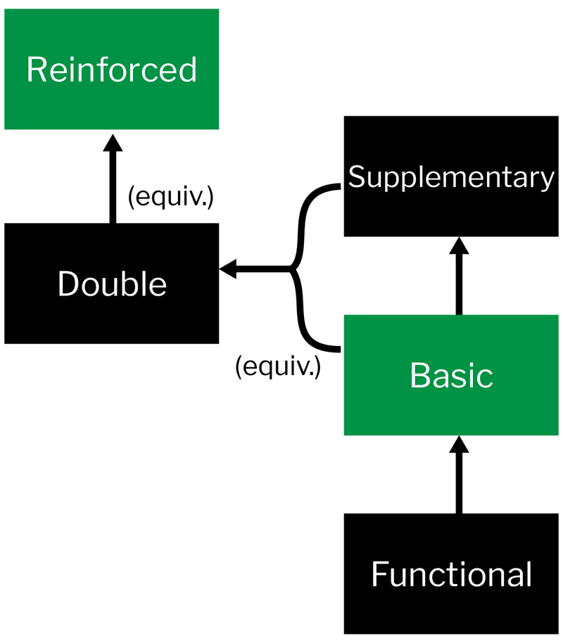
Functional insulation is the lowest class and does not generally require specific creepage and clearance spacings, but rather only requires whatever insulation is needed for the circuit to function. The first level of protective insulation requiring spacings is aptly called Basic Insulation. It is a single level of insulation that, as the name suggests, provides a basic level of protection from live electric circuits. When more insulation is required, a separate level of protection called Supplementary Insulation is added. Basic and Supplementary together constitute Double Insulation.
Double insulation consisting of Basic and Supplementary can be (and most often is) replaced by a single equivalent level of insulation called Reinforced. This relationship is summarized in figure 5, with Basic and Reinforced being the most commonly used.
Click image to enlarge
Figure 5: Insulation Classes
Working Voltage
Working voltage is the voltage across any particular insulation while the equipment is supplied at rated voltage under normal operating conditions. It is important to remember that the working voltage does not include unexpected events like surge voltage, but rather is the highest voltage stress expected across the insulation during normal operation.
Overvoltage Category
To properly design and rate a transformer, the type of overvoltage that might be expected during the application lifetime must be determined. This of course depends quite a bit on the source voltage, whether it is battery connected or grid-tied, and if grid-tied it makes a difference where on the grid it will be connected. An overvoltage classification is assigned, ranging from Class 1 being the most protected and no overvoltage expected, such as buildings or secure cabinets that have special protection devices or circuits to mitigate potential overvoltage occurrences. Class 4 at the other end of the scale is equipment installed directly near the power generation end of the grid and therefore subject to the most overvoltage variation.
Pollution Degree
Pollution degree classifies the application air environment into one of three possible categories. Pollution Degree 1 is for environments with no expectation of air/dust/humidity contamination such as in a properly sealed box, whereas Pollution Degree 3 represents an environment in which the highest level of conductive pollution is expected.
Altitude
Altitude above sea level specifically impacts the required clearance distance. At high altitudes, electrons have longer free paths to move before collisions and thus electric sparks flow more easily. Because clearance spacing is intended to prevent breakdown and current flow through air, standards require that clearance spacings be increased for any expected use at altitudes higher than 2,000 m.
Insulation Material Group
Since creepage distance intends to eliminate breakdown or current flow on a surface, it follows that the required creepage be adjusted for different surface materials. Insulating materials are rated by manufacturers with a Comparative Tracking Index (CTI) and assigned to Insulation Group 1, 2, or 3, with Group 1 materials having the highest CTI and therefore allowing the smallest creepage distance.
Click image to enlarge
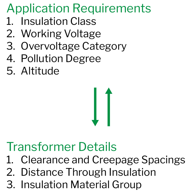
Figure 6: Summary of Insulation Requirements and Transformer Details
Summary
Designing transformers requires matching transformer construction details to the appropriate application requirements (Fig. 6). Readers will note this article did not mention specific creepage/clearance numbers or show specific safety standards tables. That will largely remain the task of transformer designers. Providing efficient and safe designs, however, requires all stakeholders to convey the proper application requirements and speaking the language of safety is the first step.