The Influence of a Power Supply Measurement Setup

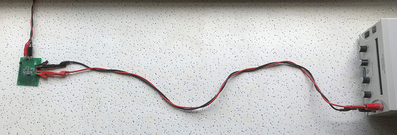
Figure 1: Arbitrarily arranged connection line between a power supply board and load
When designing a power supply, it is important to test it intensively. For this task, hardware measurements are indispensable. Of course, a multitude of mistakes can creep in during such measurements. In this short power management tip, we will take a look at the effect of the connection line between the power supply under test and the load. If a board is quickly connected in the lab, the setup often looks like the one in Figure 1. Here, a long connection line connects the power supply under test to an electronic load, shown at the right. The two leads are lying arbitrarily with a relatively large loop area on the laboratory table.
A much tidier setup is shown in Figure 2. Here, the two leads are twisted around each other to minimize the loop area in the circuit. In theory, this should lower the parasitic inductance of the connection line between the power supply undertestand th eload.That’s as far as the theory goes. But what effect do the different setups from Figure 1 and Figure 2 have on the measurements? To check this, we connected an ADP2386 evaluation board as a buck converter for an output current of up to 6 A in the two different arrangements shown in Figure 1 and Figure 2, and then measured the output voltage response to load transients. This would show the real effect of an optimized connection line position. In the example, the ADP2386 converts a supply voltage of 5 V to an output voltage of 3.3 V. The load transient is generated with an electronic load and switches from 10 mA to 4 A within approximately 30 µs. In both cases, the connection line is 1 m long.
Click image to enlarge
Figure 2: Carefully arranged connection line between a power supply board and load
Click image to enlarge
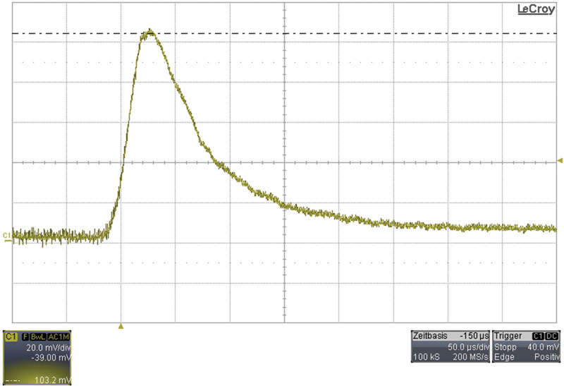
Figure 3: Output voltage load transient response with the connection line arranged arbitrarily as in Figure 1.
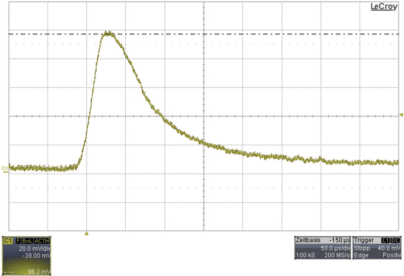
Figure 3 shows the voltage spike in the ac-coupled output voltage during the load transient response with a measurement setup as shown in Figure1. The peak value is approximately 103 mV. In contrast, Figure 4 shows the measurement using a connection line with the leads tidily twisted around each other as in Figure 2. Here, the voltage spike in the output voltage is only approximately 96 mV. This corresponds to a difference of approximately 7 mV, which shows that the tidy arrangement of connection lines results in an approximately 7% improvement for this load transient test.
Click i mage to enlarge
Figure 4: Output voltage load transient response with connection line arranged carefully as in Figure 2.
We can thus clearly see that a tidy measurement setup delivers much more exact results. Apart from the geometrical arrangement of the connection line between the power supply under test and the load, the cable length and the respective connection type—that is, alligator clips in this example or a solder joint—are also important. A shorter line has less parasitic inductance and less of an effecton the result of a load transient test.The shortest possible connection line should always beused.
Thus, it can be stated that leads twisted tidily together definitely have an effect on the measurement results, and therefore the additional effort needed to twist the leads for the measurement setup isjustified.