Author:
David Butkiewicus, Product Manager, Advantest
Date
02/20/2025
 PDF
PDF

Click image to enlarge
Figure 1. The various BMS functional blocks can be tested using the instruments listed in the parentheses.
Batteries are the ubiquitous powerhouses running portable electronics, power tools, energy-storage systems, e-bikes and e-scooters, and electric automobiles and buses. For optimum performance, battery packs in such products require sophisticated battery-management-system (BMS) ICs to optimize performance and maximize battery life. The BMS and associated circuitry has four primary tasks:
· It controls charging, whether from a 120-VAC onboard charger or an 800-VDC fast charging station.
· It performs fuel gauging and cell monitoring, indicating the battery’s state of charge based on voltage and temperature and number of charge-discharge cycles.
· It handles cell balancing, which accounts for cell-to-cell variations within a stack to optimize capacity and lifetime. Passive balancing (at 100 mA) is now common, with active balancing (1 to 10 A) on the horizon.
· It provides cell protection, taking corrective action in response to over and under voltage conditions, overcurrent faults, and over temperature conditions.
Figure 1 shows a block diagram of a generic BMS IC for a typical electric vehicle (EV) application. Along the left are monitoring inputs for each cell (V1 through Vn). Along the top are protection signals (signified by FUSE) as well as charge (CHG), discharge (DSG), and preregulation (REG1 and REG2) pins, while along the bottom are current-sense inputs (SENSE+ and SENSE-) and battery-pack temperature inputs (T1 through Tn). Finally, along the righthand side are digital I/O pins (DIO1 through DIOn) for interfacing to a microcontroller unit (MCU) or another external digital communications device. The entire assembly connects to the battery-charger positive and negative inputs, labeled PACK+ and PACK- in the figure.
BMS IC test requirements
The BMS ICs, in turn, require extensive testing to ensure they can accurately monitor the battery's state of health. The required tests are becoming increasingly stringent as single BMS ICs handle more and more cells. Typical applications today involve up to 18 cells, but 20- to 24-cell stacks are becoming increasingly common. In addition, 28-cell stacks are starting to appear, with 32-cell stacks on the near horizon. Effective test requires instruments that can force and measure voltages of up to 150 V with accuracies of less than 100 µV on each cell-monitoring input.
Specific test functions include cell emulation, which can test the BMS IC without using real batteries. Cell emulation requires forcing a stable input voltage per simulated cell, and the instrument must establish voltage conditions dependent on the state of charge of the simulated cell. Cell-monitoring capability requires tests of the BMS IC’s analog-to-digital converters (ADCs) as well as ADC trimming. The tests must ensure that the BMS can accurately monitor current as well as read battery-pack temperature sensors. Finally, the tester must test a BMS IC’s cell-balancing capability by performing RDS-ON measurements at high common-mode voltages.
Test configuration variants
For cell emulation, a tester can employ one of several cell-simulation variants, each with cost and performance tradeoffs. The resistor ladder variant (Figure 2a) offers stable voltages and low noise and is inexpensive. However, it is subject to leakage currents that must be calibrated out, and the resistor values change as the resistors heat up. In addition, this variant will exhibit accuracy issues if the ADCs pull significant currents and the variant consumes considerable load-board space.
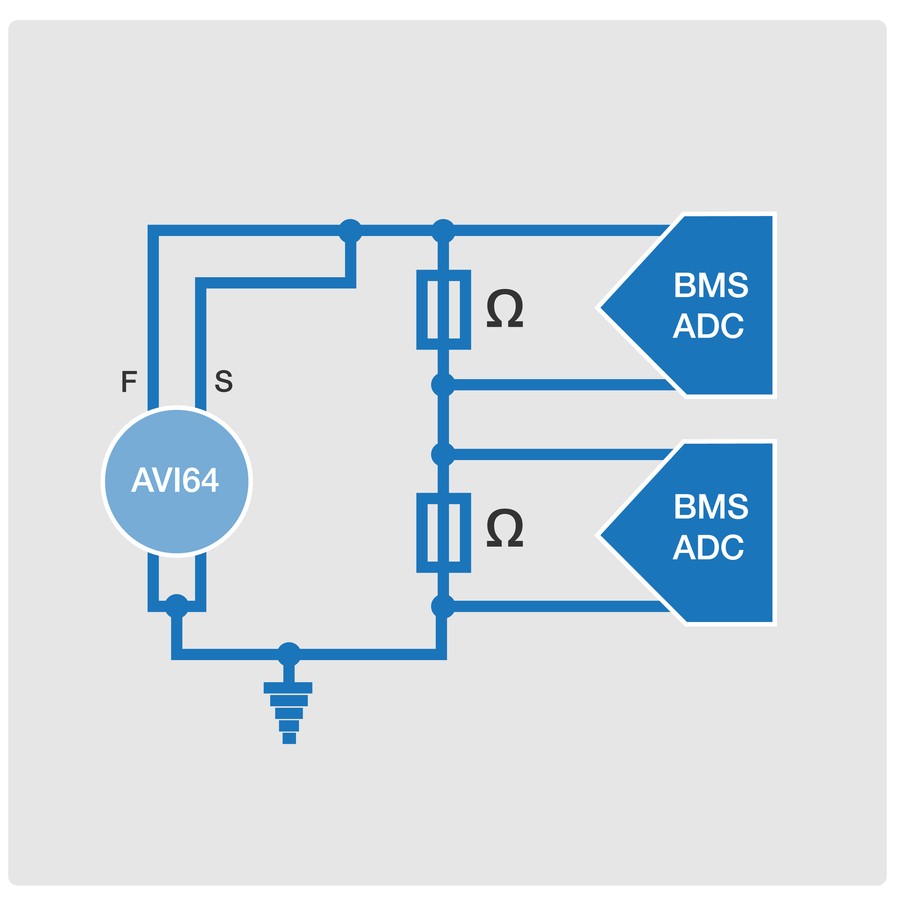
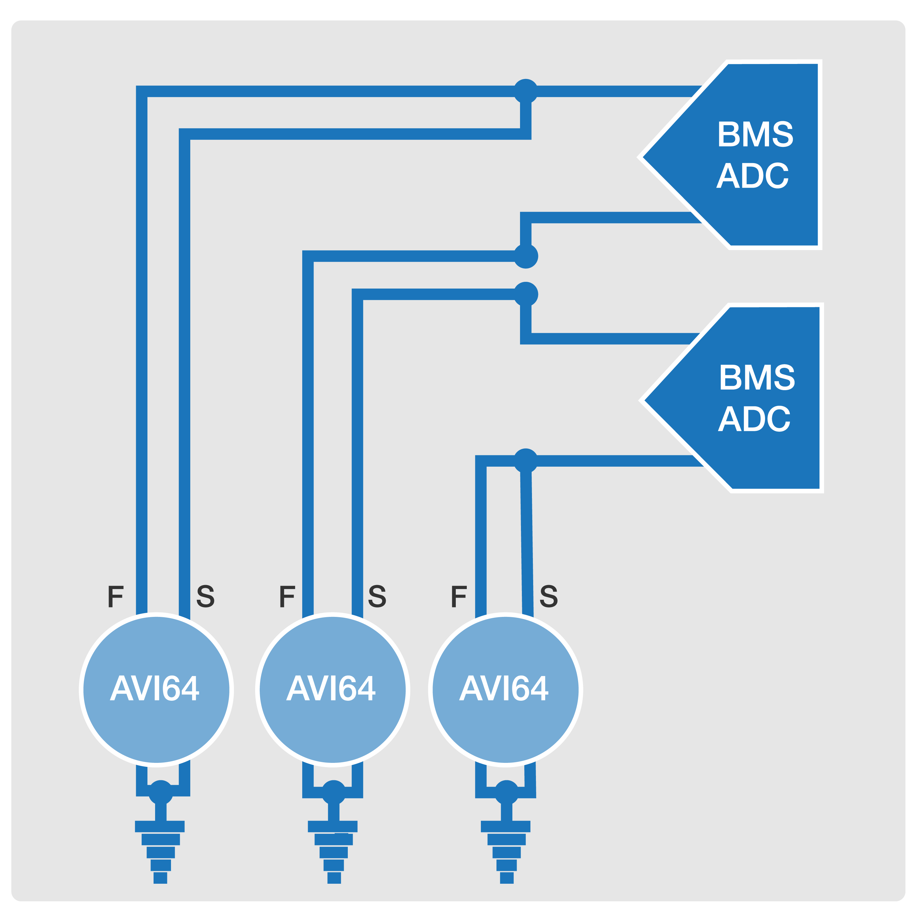
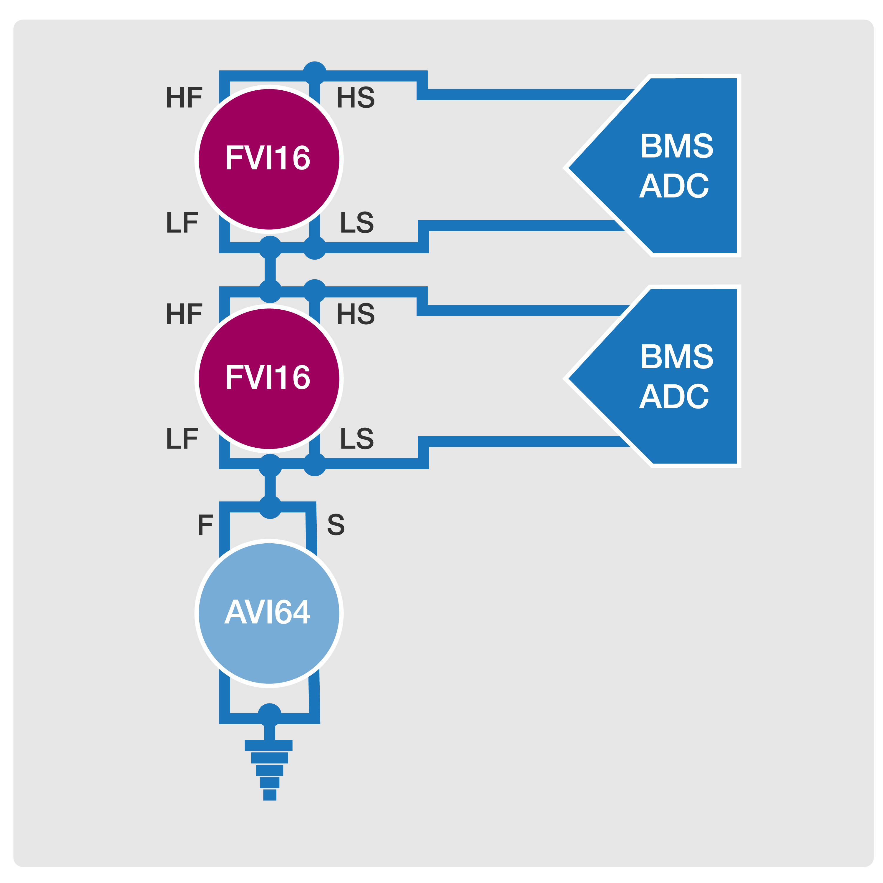
Click image to enlarge
Figure 2. Resistor ladder (a), single-ended (b), and floating (c) variants can provide BMS cell simulation.
The single-ended variant (Figure 2b) simplifies load-board design, and some single-ended instruments can support differential voltage measurements. However, instrument accuracy can degrade at higher voltage levels, and compared to the resistor-ladder variant, the single-ended approach is resource-intensive. Finally, the floating variant (Figure 2c) employs a ground-based source as a pedestal on which floating instruments sit, allowing the floating instruments to operate at a lower range with greater accuracy. This variant provides stable and precise voltage at every channel and minimizes temperature sensitivity. However, it is also resource-intensive, so efficient multiplexing is required to keep the cost of test down. The V93000 supports all three variants, including hybrid solutions, to meet the individual requirements of the DUT and to best match available system configurations.
BMS accuracy
BMS accuracy is a key consideration that has implications for test. For safety, cells are ideally cycled between 90% charge and 10% discharge levels. To maximize battery lifetimes, respective values of 80% and 20% are often used. For typical lithium-ion chemistries, the change in voltage (DV) from 90% to 10% capacity can be approximately 500 mV, while DV from 80 to 20% is only about 100 mV. If BMS accuracy is within 5% (about 5 mV) for the 80%/20% characteristic, the usable cell capacity would be limited to 75%/25%.
To recover usable device capacity, a BMS would achieve a 1-mV device accuracy specification, and under the 10:1 rule, the ATE required to test it would need 100-µV accuracy. Floating instruments offer significant advantages in conducting tests with 100-µV accuracies compared with ground-based instruments, which do not offer sufficient resolution at high voltage levels.
Instruments for BMS IC test
Advantest offers several instruments for its V93000 automated test equipment (ATE) platform to facilitate the test of BMS ICs, including the Pin Scale 5000 digital card, the AVI64 analog and power card, and the FVI16 floating voltage/current (VI) source. In Figure 1, each instrument is listed in blue in the functional blocks that it can test.
The PS5000 can handle BMS IC digital test. It supports communications link and scan testing at speeds of up to 5Gb/s with 256 channels per card and a deep vector memory. Featuring a per-pin parametric measurement unit (PMU), the protocol-based board supports SPI, JTAG, I2C, and other digital I/O interfaces to test a BMS IC’s communication with a host microcontroller unit (MCU). In addition to testing a BMS IC’s digital I/O signals, the PS5000 can also test a BMS IC’s charge and discharge control signals and exercise the overvoltage protection.
The 64-channel AVI64 module employs Advantest's universal analog pin architecture to extend the V93000 platform's capabilities to include the testing of power and analog signals. The AVI64 includes per-pin arbitrary waveform generators (AWGs) and digitizers, per-pin high-voltage time measurement units (TMU), and per-pin high-voltage digital I/O. Furthermore, the AVI64 offers floating high-current and differential-voltage measurements as well as an integrated analog switch matrix and the ability to precisely measure voltage and current parameters simultaneously at every pin. It finds use in BMS IC cell monitoring and balancing test and can be used in all three variants shown in Figure 2. In addition, it finds use in BMS IC current and temperature sensing test.
Finally, each channel of the FVI16 floating-power VI source for testing BMS ICs can supply 250 W of high-pulse power and up to 40 W of DC to test the latest generation devices while conducting stable and repeatable measurements. The FVI16 features a digital feedback loop design, which provides improved source and measurement accuracy compared to systems that operate with traditional analog feedback. Sixteen channels with four-quadrant operation allow for efficient parallel testing. For high-voltage BMS testing, cell stack voltages of up to 200V can be achieved, which meets the requirements of today’s and foreseeable future BMS devices. Like the AVI64, the FVI16 finds use in cell monitoring and balancing test, and as shown in Figure 2c, it can work with the AVI64 in the floating cell-simulation variant.
Future BMS innovations
BMS technology is evolving to provide ever higher levels of performance and efficiency. One emerging innovation is the wireless BMS (wBMS), which promises to eliminate about 3 kg of wiring-harness weight of the total 35 to 90 kg of wiring harness weight in a typical EV (Figure 3). Wiring harnesses not only add weight, but they also add cost and complexity and take up valuable space, and harnesses and connectors are common failure points that can compromise reliability and safety.
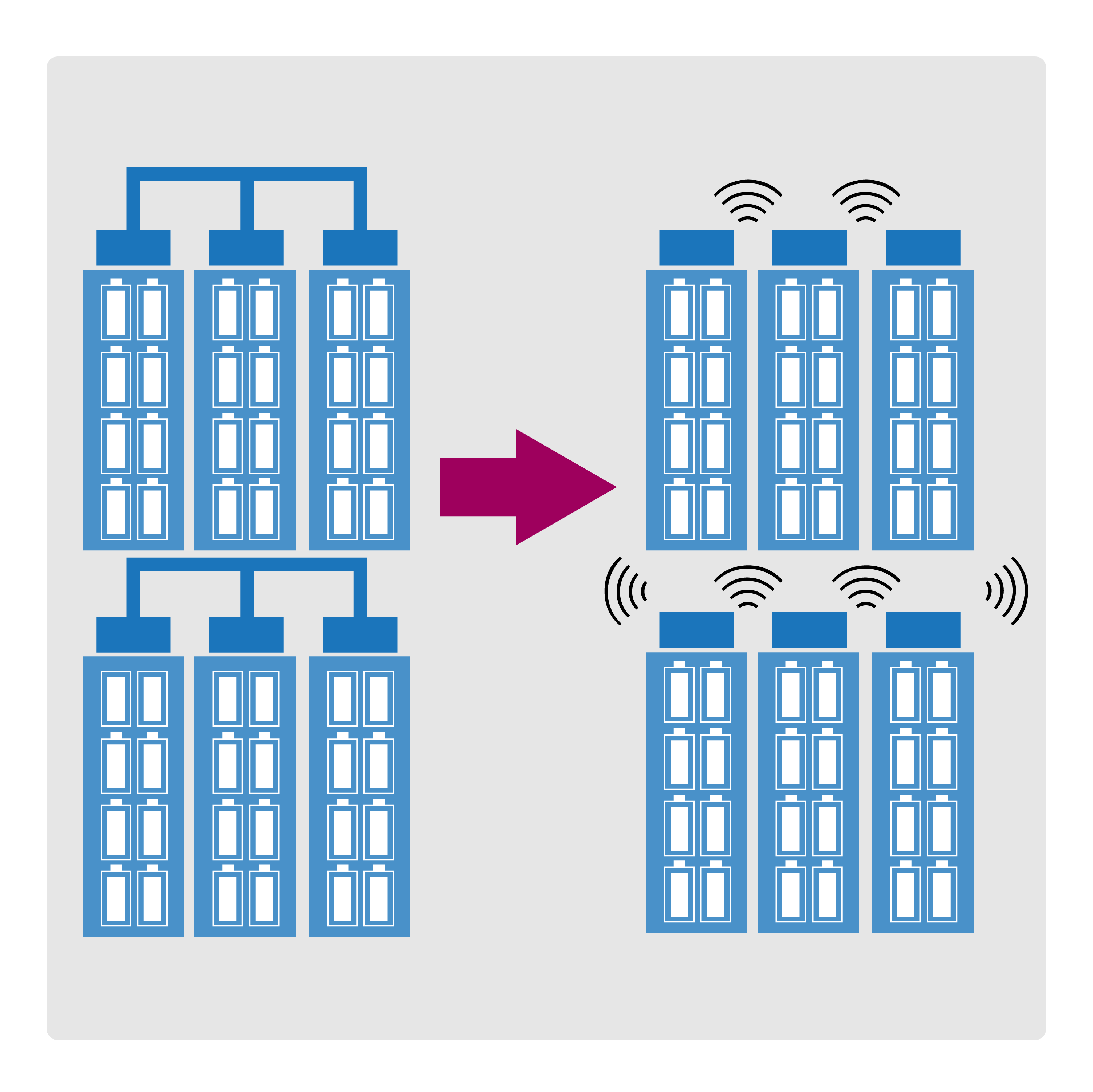
Click image to enlarge
Figure 3. The wired BMS (left) faces competition from the wBMS (right), which saves space and weight and removes potential points of failure.
Compared with a wired BMS, a wBMS is estimated to save 90% of wiring weight and 15% of total battery-pack volume. Major vendors are already offering wBMS implementations. The V93000 platform has a long history of success in performing wireless test and is fully suited to performing both the RF and power/analog tests required for a wBMS IC.
Another emerging BMS innovation is electrochemical impedance spectroscopy (EIS), which improves on simple voltage and temperature measurements to determine the state of health, state of charge, remaining range, and other battery parameters. EIS involves applying a small AC voltage from less than 1 Hz to about 10 kHz across the battery and measuring the resulting AC current response to derive the frequency-dependent battery impedance. The impedance, in turn, indicates a battery’s internal processes, including ion mobility, charge transfer, and diffusion. EIS devices already on the market include a low bandwidth loop (less than 200 Hz), a high bandwidth loop, a precision analog/digital converter (ADC), and a programmable switch matrix, all of which can be readily tested using the V93000 ATE system.
Conclusion
The market for BMS ICs, which enable battery charging and protection, cell balancing, and state-of-charge estimation, is rapidly expanding, driven by electric vehicles and mobile tools. Scalable and flexible ATE is keeping pace with BMS advances, with instruments available for addressing higher voltages and finer accuracies, and it is well prepared to address the RF test challenges as wBMS technology advances. While this article focused on EV BMS applications, BMS technology has an equally important role to play in applications ranging from portable electronics to power tools. Advantest’s platform is suited for today's and tomorrow’s testing requirements for all BMS devices, including those with RF capabilities.