Author:
Abdel-Rahman Sam, Senior Principal System Architect, Wide-bandgap technology for renewable energy-based storage applications
Date
08/21/2024
 PDF
PDF

Click image to enlarge
Figure 1: ESS integrated with solar inverter
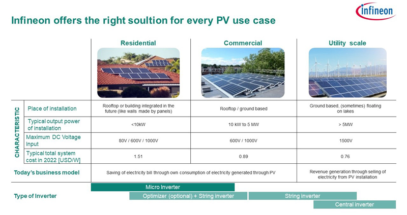
ESS in residential solar installations
Gradual but consistent improvements in the efficiency of residential solar generation systems have been instrumental in their growth around the world. This resulted in a generation of about 510 GWh of renewable energy in 2023, about 75 percent of which was from residential solar [1]. The role of energy storage systems (ESS) in solar photovoltaic (PV) systems is important as it allows for the optimization of generated energy. They are, in fact, essential throughout the renewable energy sector, as they mitigate the operational risks posed by the unpredictable nature of renewable energy generation, influenced by weather conditions.
Traditional residential solar energy systems rely on inverters to convert solar power to AC electrical power during daylight hours, with excess power potentially sold back to utility companies. However, during non-daylight hours, end-users rely on the utility's electricity supply. Utility companies adjust their pricing models to account for these limitations, implementing "time-of-use" rates that are higher when solar power is unavailable.
To address the problem of variable pricing, a behind-the-meter ESS is employed. This enables users to protect themselves from high energy costs through 'power peak-shaving’, helping grid balancing and optimizing the utilization of renewable energy. It involves storing excess energy generated during off-peak hours and discharging it during peak hours when electricity demand and prices are higher. When paired with an inverter, the demand for AC power can be met by the residential solar system at any time, providing a reliable and stable power supply. This arrangement ensures that renewable energy sources can maintain a consistent output, regardless of external factors, making them a more viable and efficient option for power generation.
This article, the final installment of the four-part series on residential solar systems, focuses on the importance of silicon carbide (SiC) in ESS of residential solar power systems. It includes a simulation study comparing the performance of conventional insulated gate bipolar transistors (IGBT) and CoolSiC MOSFETs using the IPOSIM Infineon Power Simulation Tool (PLECS) tool [2].
Adding storage elements like batteries to an existing solar installation combines the original power generation path (solar panels to inverter) with a new power storage path (converter to battery). In a converter with storage capabilities, there are three primary power blocks, with the first two stages being similar to those in string inverters without storage. The third one is the DC-DC conversion stage, which is responsible for charging a battery pack from the DC link, distinguishing it from the Maximum power point tracking (MPPT) converter power stage.
Unlike the MPPT converter, the DC-DC converter must be bidirectional, enabling it not only to charge the battery pack from the DC link but also convert the stored energy in the battery pack back to the DC link voltage when needed. Their bidirectional capability is essential in enabling the efficient and flexible use of energy stored in the battery pack. The bidirectional power topology enabled by the DC‑coupled ESS are simpler to implement as they eliminate the need for the bidirectional AC-DC conversion stage. This enhances the conversion efficiency and reduces the bill of materials (BOM).
Key challenges in ESS designs
Key challenges in ESS design include achieving smaller size and weight reduction for better power density, improving overall system efficiency, lowering costs per watt, and maintaining reliable bidirectional energy flow. Overcoming these challenges is vital for the ongoing advancement and implementation of ESS, as they become increasingly essential components in renewable energy systems and grid stability.
As the battery’s storage capacity in renewable applications continues to grow, engineers and designers face the ongoing challenge of increasing efficiency, power density, and reliability in their system designs. A significant trend influencing ESS design is the evolution of wide bandgap (WBG)-based power transistors like SiC MOSFETs.
Benefits of CoolSiC technology in ESS
Infineon offers a wide portfolio for WBG power transistors. One such solution is the CoolSiC MOSFET family, which offers several advantages over conventional silicon IGBTs for ESS. One of the primary benefits of CoolSiC technology in ESS is its high switching frequency. This allows for the reduction of passive component size, which in turn reduces the size and weight of the ESS system. It also enables smaller magnetics, which allows a higher power density. Additionally, the CoolSiC MOSFET technology can integrate multiple functions into a single device, saving space and reducing the number of components required in the system.
It also offers lower switching losses compared to conventional silicon-based devices. This allows power conversion systemsto handle increased power ranges. Furthermore, lower losses result in better thermal performance and thereby smaller heatsinks, reducing the bill of materials (BOM) and contributing to cost savings [3,4].
CoolSiC MOSFETs and diodes for ESS
The ESS often utilizes a common DC-AC power stage in string and hybrid inverters to achieve the bidirectional functionality, allowing for both charging and discharging of the battery in the ESS. The available common power stages include two-level H-bridge, highly efficient and reliable inverter concept (HERIC), three-level transistor neutral point clamped topology (3L-TNPC), and three-level active neutral point clamped (3L-ANPC), which are capable of bidirectional operation [5].
HERIC is a popular choice among available single-phase DC-AC stages due to its filtering capability and isolation between the grid and the PV input during freewheeling. Furthermore, CoolSiC MOSFETs are designed to support a blocking voltage ≥ 630 V (TJ of –50°C to 175°C). When combined with CoolSiC Schottky diodes, they can deliver outstanding light-load efficiency and improved full-load efficiency. The availability of these components in packages like PG TO-247-3 allows designers to create high power density hybrid inverters. It also allows designers to implement a Kelvin source configuration, which can reduce switching losses and increase switching speeds.
Subsequently, a simulation study comparing IGBTs and CoolSiC MOSFETs using the HERIC inverter topology was performed to explore the advantages of CoolSiC MOSFETs.
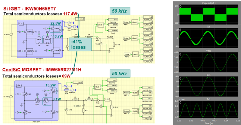
Figure 2and Figure 3 show the highlights of the performance comparison between silicon (Si) IGBTs and silicon carbide (SiC) MOSFETs in a HERIC inverter stage in the same topology under the same condition. The inverter is rated for 6 kW and operates with an input voltage of 400 V and an output voltage of 230 V. The HERIC inverter stage is a practical use case for CoolSiC™ MOSFETs, demonstrating their superior performance and figures of merit (FOMs) compared to silicon IGBTs. The HERIC inverter stage using CoolSiC MOSFETs was simulated in PLECS to showcase the benefitsit offers in string and hybrid solar inverters.
The following are the two scenarios considered in the simulation:
1. Using CoolSiC MOSFETs at the same switching frequency to maximize efficiency benefits: In this case, CoolSiC MOSFETs can reduce the total semiconductor losses by 41 percent.
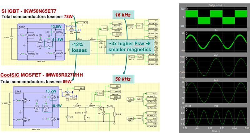
2. Using CoolSiC MOSFETs at a higher switching frequency to gain power density benefits: Here, CoolSiC MOSFETs can be switched at approximately three times the frequency, reducing the size of magnetics while also reducing the total semiconductor losses by 12 percent.
These results demonstrate the significant advantages that CoolSiC MOSFETs can offer to string and hybrid solar inverters, where high efficiency and power density are the key differentiators in a highly competitive market. Infineon offers a range of CoolSiC MOSFETs, reference designs, and support services to help solar inverter and ESS power conversion designers integrate this technology into their systems.
Click image to enlarge
Figure 2: Si vs. SiC in HERIC – 6 kW, 400 Vin, 230 V AC with same operating frequency
Click image to enlarge
Figure 3: Si vs. SiC in HERIC – 6 kW 400 Vin, 230 V AC with different operating frequency
For more information on Infineon’s offerings for renewable energy solutions, scan or click the QR code to visit our webpage. Stay tuned for the concluding article of the residential solar series, where we look at using power optimizers to get the best out of solar PV systems. Meanwhile, check out the first two articles of the series to get an overview of the critical components of a residential solar system and learn how to enhance string inverter designs for these systems.
References:
[1] International Energy Agency: Renewables 2023: January 2024; https://www.iea.org/news/massive-expansion-of-renewable-power-opens-door-to-achieving-global-tripling-goal-set-at-cop28
[2] Infineon Technologies AG: IPOSIM Infineon Power Simulation Tool (PLECS), https://www.infineon.com/cms/en/design-support/simulation-modeling/iposim-infineon-power-simulation-tool-plecs/#!videos
[3] Infineon Technologies AG: CoolSiC™ for ESS, https://community.infineon.com/t5/Blogs/CoolSiC-for-ESS/ba-p/653861
[4] Infineon Technologies AG: Silicon Carbide CoolSiC™ MOSFETs, https://www.infineon.com/cms/en/product/power/mosfet/silicon-carbide/
[5] Infineon Technologies AG: Energy Storage Systems, https://www.infineon.com/cms/en/applications/industrial/energy-storage-systems/