Author:
Damijan Zupancic, application marketing for residential solar and energy storage systems
Date
08/21/2024
 PDF
PDF

Click image to enlarge
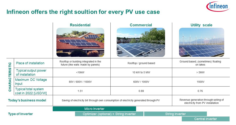
Figure 1: Power optimizer in a residential solar installation
In the quest for a greener, more sustainable future, residential solar installations are growing rapidly around the world, with 2023 seeing 365 GW of new installations [1]. As the world embraces residential solar, maximizing the efficiency of these systems becomes more and more vital. This is where power optimizers come into play – they greatly improve the efficiency of solar PVs by optimizing power output at the point of power generation itself – the solar panels. This article is Part 3 of our 4 part series on residential solar, aimed at using power optimizers to enhance the efficiency of residential solar systems.
Solar optimizers are small electronic devices aimed at optimizing the efficiency of individual solar panels, maximizing the overall energy yield of the solar PV. They achieve this by regulating the DC electricity output from each solar panel, converting it into a more efficient form, and minimizing energy losses due to factors like shading, dust, or misalignment.
Solar optimizers use maximum power point tracking (MPPT) to adjust the voltage and current to maximize power output in varying conditions, allowing each panel to operate independently at peak efficiency. This results in increased overall efficiency and output, flexible system design, and detailed monitoring of each panel's performance – even under extreme environmental conditions.
Creating an efficient optimizer involves several critical components, starting with power transistors – transistors with minimal conduction and switching losses are essential to maximize the power output of the power optimizer itself. Since power optimizers need to operate in less than ideal environmental conditions, reliability in a wide range of temperature and voltage is another vital consideration.
Gate drivers control the power transistors, ensuring they switch on and off at the right times. Efficient gate drivers are essential for reducing switching losses and maintaining the reliability of the power optimizer. They must be capable of handling high switching frequencies to improve the overall performance of the MPPT.
As the brains of the optimizer, microcontrollers (MCUs) execute the MPPT algorithms that determine the optimal operating point for each panel. An efficient MCU must be capable of handling complex calculations quickly and accurately, as well as monitoring various parameters such as voltage, current, and temperature.
To improve the efficiency of the solar PVs, Infineon has designed a compact 600 W buck solar power optimizer releasing in September of 2024. Designed to be the best mix of cost and efficiency on the market, it uses the following Infineon components (among others):
Click image to enlarge
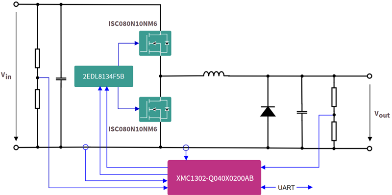
Figure 2: Block diagram of the 600 W buck solar optimizer
As with any electronic device, power optimizers need components with minimal losses for maximum operational efficiency. To maximize the power harvested from the solar panel, Infineon’s OptiMOS™ 6ISC080N10NM6 [2] offers exceptionally low RDS(ON) and reverse recovery charge, minimizing conduction, and switching losses. The high avalanche rating and operating temperature of these switches ensure reliability and durability under the demanding conditions that power optimizers typically need to operate in.
To optimally drive these switches, the power optimizer uses EiceDRIVER™ [3] gate driver ICs with tight propagation delay matching, an active miller clamp, and a wide output supply range. These junction-isolated gate drivers enable faster turn-on with lower losses and a shorter deadtime, prevent parasitic turn-on, and protect the power switches from damage during short circuit conditions. 2EDL8134-F5B is designed to drive both high-side and low-side MOSFETs in a half-bridge configuration. The IC only needs a minimum number of external components and features a 120 V integrated bootstrap diode.
Equipped with the MATH co-processor and temperature sensors, the XMC1302-Q040X0200 AB MCU with Arm® Cortex®-M0 [4] ensures precise control of the MPPT algorithms. It also accurately measures voltage and temperature to enable real-time response to varying environmental conditions.
Any hardware operates best only in conjunction with equally good software. Infineon’s solution also displays a great synergy between the two. The firmware for the power optimizer is developed on the homegrown, open-source DAVE™ IDE [6]. Downloading the latest version of the IDE will provide access to the project with the files containing the main body of the source code, the main structure describing the MPPT algorithm, as well as the necessary function calls for the current and voltage loops.
Click image to enlarge
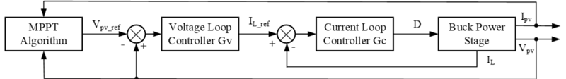
Figure 3: Control-structure loop including the P&O algorithm for the MPPT
MPPT operates using algorithms like perturb and observe (P&O), which help optimize the efficiency of solar panels. It functions by periodically perturbing, or slightly adjusting, the voltage of the solar panel and observing the resulting change in power. If the power increases, the perturbation continues in the same direction and it is reversed if the power decreases. This process is repeated continuously to keep the solar panel operating at its maximum power point, ensuring maximum energy is harnessed from the available sunlight.
According to internal tests, the 600 W buck optimizer demonstrated a maximum efficiency of >98.5 percent and an MPPT efficiency of >99 percent over a wide range of MPPT voltage (12-80 V). The design uses a 15 µH inductor to limit the ripple current between 30 and 40 percent. It also exhibited a switching frequency of 200 KHz, leading to a compact system design.
For the test, the duty cycle was set to a 75 percent and the input voltage was increased from 40 V to 80 V in 10 V increments. Measurement points were taken at 1 A output current intervals, continuing until either the 10 A input current limit or the 600 W output power limit was reached. The following graph shows the power electronics efficiency at different input voltages:
Click image to enlarge
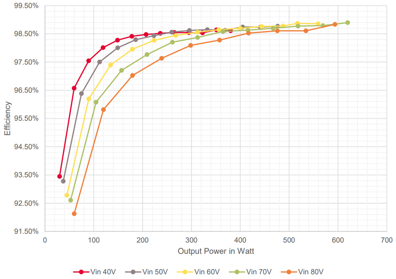
Figure 4: Power electronics efficiency measurement at different input voltages
As shown in the figure, the efficiency is higher at low input voltages due to the lower switching losses and a more efficient auxiliary power supply. At
output current 5 A or higher, the efficiency becomes nearly independent of the input voltage. It also shows a higher power electronics efficiency at higher output powers. For Vin = 80 V and Iout = 10 A, the calculated losses were only 6.54 W, including switching, conduction, shunt, inductance, and auxiliary losses.
To calculate the MPPT efficiency, a PV module with a power supply of 80 V/18 A and a load of 650 W power dissipation was connected. The test has shown an average MPPT efficiency of 99.15 percent, peaking at 99.44 percent.
As for the limitations of this design, the board uses a top-side cooled heatsink with convective heat transfer for heat dissipation. Since the power transistors used in these designs are bottom-side cooled devices, the thermal performance can be improved by swapping these with their top-side cooled counterparts. For even higher efficiency, the auxiliaries and the shunt section of the board can be changed to reduce the associated losses. The MCU can be replaced with a PSoC™ 32-bit high-performance MCU [5] built on a dual-core Arm® Cortex®-M architecture can increase energy efficiency by offloading tasks to different cores – high-powertasks to the M4 and low-power tasks to the M0+. Infineon is committed to improve the product design over time by changing just a few components.
Check out the first three articles of the residential solar series, where we talk about the different critical components of a solar PV system, delving deeper into string inverters, and energy storage system designs respectively.
As we conclude this series on residential solar systems, it is clear that power optimizers are essential to creating energy-efficient solar PV systems. To that end, following the release of Infineon’s 600 W buck power optimizer in September 2024, designed for an optimal mix of cost and performance, Infineon is set to release a 400 W buck-boost version.
But that’s only a part of the puzzle. In line with its commitment to supporting the transition to renewable energy, Infineon offers a plethora of power electronics products to design the ideal solar solution for all needs. Click or scan the QR code to explore Infineon’s comprehensive portfolio.
References
[1] S&P Global Commodity Insights: PV Inverter Market Tracker: Q1 2024: April 03, 2024
[2] Infineon Technologies AG: ISC080N10NM6; https://www.infineon.com/cms/en/product/power/mosfet/n-channel/isc080n10nm6/
[3] Infineon Technologies AG: EiceDRIVER™ 2EDN Gate Driver for MOSFETs; https://www.infineon.com/cms/en/product/power/gate-driver-ics/eicedriver-2edn-gate-driver-for-mosfets/
[4] Infineon Technologies AG: XMC1302-Q040X0200 AB; https://www.infineon.com/cms/en/product/microcontroller/32-bit-industrial-microcontroller-based-on-arm-cortex-m/32-bit-xmc1000-industrial-microcontroller-arm-cortex-m0/xmc1302-q040x0200-ab/
[5] Infineon Technologies AG: 32-bit PSoC™ Arm® Cortex® Microcontroller; https://www.infineon.com/cms/en/product/microcontroller/32-bit-psoc-arm-cortex-microcontroller/
[6] Infineon Technologies AG: DAVE™ IDE; https://softwaretools.infineon.com/tools/com.ifx.tb.tool.daveide