Reliability and Performance for Motor Control Encoders

Rotary encoders are often used for electric machines where the encoder is connected to the rotating shaft to provide feedback for the control system
Figure 1: Using RS-485 to interface between the absolute encoder slave to servo drive master for closed-loop control of an ac motor
The primary purpose of a motor control encoder is to measure angular position and speed measurement. Figure 1 shows a motor control signal chain using RS-485 transceivers and microprocessor to interface between the absolute encoder (ABSencoder) slave and industrial servo drive master for closed-loop control of an ac motor. Analog Devices’ ADM3065E RS-485 transceiver is designed for reliable operation in harsh environments such as motor control encoders, with added noise immunity and (IEC) 61000-4-2 ESD robustness.
Noise Immunity
RS-485 signaling is balanced, differential, and inherently noise immune. System noise couples equally to each wire in an RS-485 twisted pair cable. One signal emits the opposite of the other signal, and electromagnetic fields coupled on to the RS-485 bus cancel each other out. This reduces the EMI of the system. In addition, the enhanced ADM3065E 2.1 V drive strength allows greater SNR in communications. Adding signal isolation to the ADM3065E can be easily implemented using the ADuM141D. The ADuM141D is a quad-channel, digital isolator based on Analog Devices iCoupler technology. The ADuM141D can operate at a data rate of up to 150Mbps, making it suitable for operation with the 50Mbps ADM3065E RS-485 transceiver. Direct power injection (DPI) measures the ability of a device to reject noise that is injected into the power supply or input pins. The isolation technology used in the ADuM141D has been tested to the DPI IEC 62132-4 standard.

Click image to enlarge
Figure 2: Signal isolated, 50 Mbps RS-485 solution (simplified diagram—all connections not shown)
IEC 61000-4-2 ESD Performance
ESD on the exposed RS-485 connectors and cabling for the encoder to motor drive is a common system hazard. The system-level IEC 61800-3 standard relating to EMC immunity requirements for adjustable speed electrical power drive systems requires a minimum ±4 kV contact/±8 kV air IEC 61000-4-2 ESD protection. The ADM3065E exceeds this requirement with ±12 kV contact/±12 kV air IEC 61000-4-2 ESD protection. Figure 3 shows the 8 kV contact discharge current waveform from the IEC 61000-4-2 standard compared to the human body model (HBM) ESD 8 kV waveform. Figure 4 shows that the two standards specify a different waveform shape and peak current from one another. The peak current associated with an IEC 61000-4-2 8 kV pulse is 30 A, while the corresponding peak current for the HBM ESD is more than 5× less, at 5.33 A. The other difference is the rise time of the initial voltage spike, with IEC 61000-4-2 ESD having a much faster rise time of 1 ns, compared to the 10 ns associated with the HBM ESD waveform. The amount of power associated with an IEC ESD waveform is much greater than that of an HBM ESD waveform. The HBMESD standard requires the equipment under test (EUT) to be subjected to three positive and their negative discharges—while in comparison, the IEC ESD standard requires 10 positive and 10 negative discharge tests. The ADM3065E with the IEC 61000-4-2 ESD ratings is better suited for operation in harsh environments compared to other RS-485 transceivers that state varying levels of HBM ESD protection.

Click image to enlarge
Figure 3: IEC 61000-4-2 ESD waveform at 8 kV compared to the HBM ESD waveform at 8 kV
Click image to enlarge
Figure 4: Experimental setup
EnDat Communication Protocol
A number of communication protocols are used for encoders; for example, EnDat, BiSS, HIPERFACE, and Tamagawa. Despite their differences, the encoder communication protocols have similarities in regard to implementation. The interfaces of these protocols are serial bidirectional pipes that comply with either the RS-422 or RS-485 electrical specifications. While there are commonalties in the hardware layer, the software required to run each of the protocol is unique. Both the communication stack and the required application code are specific to the protocol. This article focuses on hardware and software implementation of the master side of an EnDat 2.2 interface.
Impact From Delays
Delays fall into two categories: first, there is the transport delay of the cable, and second, there is the propagation delay of the transceivers. The speed of light and the dielectric constant of the cable determines cable delay with typical numbers of 6 ns/m to 10 ns/m. When the total delay exceeds half a clock period, the communication between the master and the slave breaks down. At this point, the designer has the following options:
· Lower the data rate
· Bring down the propagation
· Introduce delay compensation on the master side
Option 3 compensates for both cable delay and transceiver delay and therefore is an effective way to ensure that the system can run with high clock rates on long cables. The disadvantage is that the delay compensation increases the system complexity. In systems where delay compensations are either not possible, or in systems with short cables, the value of using transceivers with a short propagation delay is evident. A low propagation delay enables a higher clock rate without having to introduce delay compensation in the system.
Master Implementation
A master implementation consists of a serial port and a communication stack. Because the encoder protocols do not comply with standard ports, such as a UART, the peripherals found on most general-purpose microcontrollers cannot be used. The implementation of the EnDat interface discussed here is done on the ADSP-CM40x from Analog Devices, which is a processor targeting motor control drives. Besides peripherals for motor control, such as pulse width modulator (PWM) timers, analog-to-digital converters (ADCs), and sinc filters, the ADSP-CM40x has highly flexible serial ports (SPORTs).
These SPORTs are capable of emulating a number of protocols, including encoder protocols such as EnDat and BiSS. Because of the rich peripheral set of the ADSP-CM40x, it is possible to perform advanced motor control, as well as interfacing to an encoder with the same device.
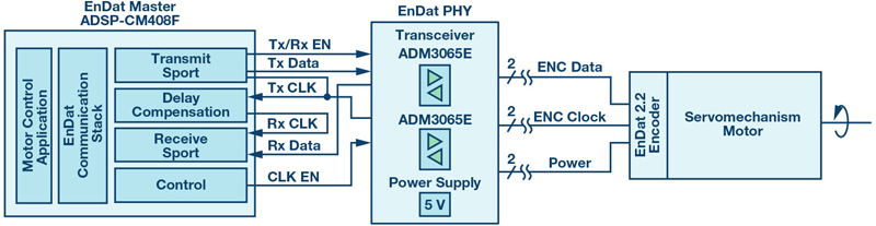
Test Setup
The EnDat 2.2 test setup is shown in Figure 4. The EnDat slave is a standard servo motor from Kollmorgen (AKM22) with an EnDat encoder (ENC1113) mounted to the shaft. Data, clock, and power linesconnect the encoder to the transceiver board. There are two transceivers and power supply for the encoder on the EnDat PHY. One of the transceivers is used for the clock and the other transceiver is used for the data line. The EnDat master is realized with ADSP-CM40x using a mix of standard peripherals and software. Both the transmit port and receive port are implemented with flexible SPORTs.
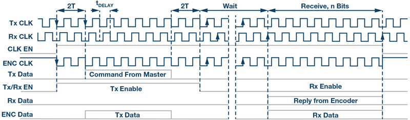
The EnDat protocol consists of a number of different frames of varying length. However, these frames are all based on the same sequence, as seen in Figure 5. First, the master issues a command to the slave, then the slave processes the command and performs the necessary calculations. Finally, the slave sends the result back to the master.
Click image to enlarge
Figure 5: EnDat transmit/receive sequence
The transmit clock (Tx CLK) is generated by the processor ADSP-CM40x. Because of delays in the system, the data from the encoder will be out of phase with the transmit clock before they get back to the processor. To compensate for transport delay, tDELAY, the processor also issues a receive clock (RxCLK), which is delayed by tDELAY compared to the transmit clock. Bringing the receive clock in phase with the data received from the slave is an effective way to compensate for the transport delay.
The clock signals from the processor are continuous, while the EnDat protocol specifies the clock must only be applied to the encoder during communication. At all other times the clock line must be held high. To handle this, the processor generates a clock enable signal, CLK EN, which is fed to the ADM3065E’s data enable pin. After exactly two clock periods (2T) the master starts clocking out the command on TxDATA. The command is 6 bits long and is followed by two 0 bit. To control the data direction through the transceiver, the processor sets Bit Tx/Rx EN high while transmitting.
When the slave is ready to respond, the data line receive data is pulled high and the response is sent immediately after. After receiving the n bits response, the master stops the clock by setting CLK EN signal low. At the same time, the ENC CLK signal goes high. The data flow is half duplex and the traffic on the combined data line is shown as ENC data.
Experimental Results
Figure 6 shows test results from the EnDat system. The clock frequency used in the test is 8 MHz and the delay compensation is achieved by phase shifting the receive clock. The bottom signal is the command from the EnDat master. The command shown here is send position, which is two 0s, followed by six 1s, and ended with another two 0s. In total, the command is 10 bits long. The response from the encoder is the third signal from the top. The combined data line is the second signal from the top. Finally, the top signal is the clock applied to the encoder.

Click image to enlarge
Figure 6: EnDat data exchange


