
Baljit Chandhoke, Product Manager for RF Products at Microchip talks to PSD about the latest innovations in power amplification for RF Systems.
PSD - First of all, could you describe a typical RF system?
BC - Figure 1 shows a typical block diagram of an RF transmitter. The receiver will have a similar layout that basically reverses the process. The data processing stage is done in digital, but since transmission cannot be digital, the first block converts the signal to analog. The resulting signal then gets amplified and up-converted to a higher frequency and then amplified further using a high power amplifier. Then it is ready to be sent to the antenna. This type of architecture is known as superheterodyne
The actual level of power amplification that is required may not be as high as you’d think. 5 to 10 W of power coming out through the antenna is all that is required to send a signal to a receiver on a satellite in a low earth orbit in the commonly used Ka- and Ku-bands.
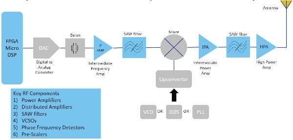
Figure 1 - Diagram showing the main blocks of an RF transmitter
PSD – Are satellite communications the major driver of innovation in this area?
BC – There are major changes going on in the satellite industry at the moment as newer technologies replace older ones. The huge antennas that you often see for satellite communications are now being replaced with phased array antennas, both to communicate from the ground station on earth to the satellite and from the satellite back to earth. These systems require smaller sized components for compact solutions, and lower weight components to allow for higher payloads and less fuel consumption in the satellite.
There are thousands of (LEO) satellites circling the earth and delivering services that include broadband internet access, navigation, maritime surveillance, and remote sensing using phased-array beamforming antennas. Another use for RF technology is in 5G fixed wireless access, for infrastructure devices like small cells, femto cells, pico cells and repeaters. It is also found frequently in aerospace and defense applications, where it is used to monitor the radar environment.
PSD – What are the critical areas of RF systems?
BC - RF systems need linear, efficient power generation. The RF spectrum is very precious, and each signal has a particular channel it must stay within. Only very low levels of noise are allowed to leak to adjacent channels, including harmonics. The higher the linearity of the power amplifier, the lower the output distortion, and that is very important for this type of use. Similarly to many other areas of electronics, the second main specification for RF amplification is efficiency. As well as the performance metrics, the physical traits of the power amplifier are also very important – size and weight, and, of course, cost. So to summarize, RF power amplification is all about generating the desired output power at the frequencies of interest, with minimum distortion and high efficiency.
To classify power amplifiers, figures of merit (FoM) are used. We define the linearity of the power amplifier in two main ways. P1dB shows at what level the power drops by 1 dB. Typically, the input power and output power track until a certain point when the power starts to saturate. The P1dB point is when there is a 1 dB drop in that linear relationship. The other main FoM for PA linearity is OIP3 (Output Third Order Intercept Point) which measures harmonic noise. Higher OIP3 and P1dB figures imply higher linearity, which results in low distortion of the RF signal output. For the efficiency FoM, the PAE (Power Added Efficiency) percentage figure is used. Efficient power is generated with a higher PAE percentage. Other components in the system have their own FoM figures.
PSD – The power industry in general has been transformed by wide bandgap materials. Is this the case in the RF power industry as well?
BC - Figure 2 shows the technology transition of materials. For lower frequencies up to 3 GHz, LDMOS provides the highest output power and is normally the technology of choice. Gallium arsenide (GaAs) provides output power up to 5 W across a wide frequency band up to 100 GHz and is the preferred solution in this band.
For high power output at high frequencies, we use two wide bandgap materials together - GaN transistors on a SiC substrate. GaN on SiC has a very high breakdown voltage and high bias voltage, which allows it to achieve the highest power density, broad bandwidths and high gain. It also has great thermal properties. GaN on SiC can generate high, linear and efficient output power at high frequencies in the Ka and Ku-bands, from 12 to 40 GHz, which makes it ideal for use in most of the industries and applications discussed earlier, including aerospace and defense, 5G, and satellite communication applications.
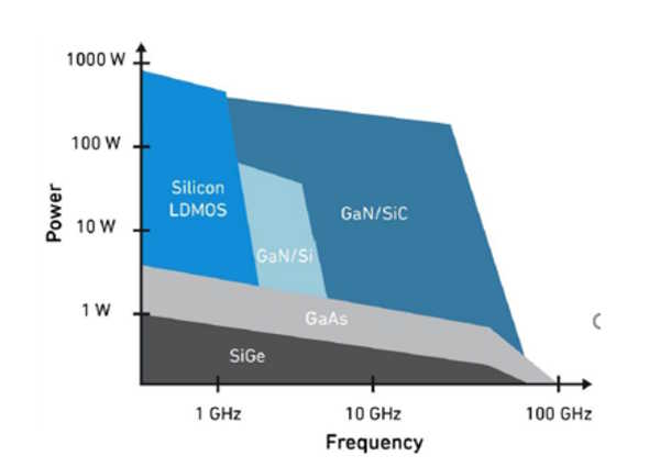
Figure 2 - Material transition for RF power amplifiers
PSD – Can you give me some practical examples of these types of products?
BC – At Microchip, we use GaN on SiC with its highest power density to get high linear efficient output power in Power Amplifier products for satellite communications, 5G, aerospace and defense applications. For example, products in our GaN on SiC Ku-band range goes right up to 50W with the ICP1747 device, or there are other products, such as the ICP1543 that cover the full Ku-band frequency range, and still can provide 20W output. For the Ka-band, we also have a wide variety of products. These include the ICP2840, which has a saturated power of 9W, operates in 27 - 31 GHz frequency range and meets all of the requirements to be used in satellite communication or 5G. To complement the power amplifier ranges, Microchip also offers a full range of RF products, including LNAs, switches, MMICs, transistors, diodes, saw filters and VCSOs.
.jpg)


.jpg)
