Intelligent Edge sensors select and process data independently to lower the volume of data transmitted between the sensors and the central control unit
Figure 1: SPoE supplies up to 52W via a single 2-wire cable up to 1km in length
A smart sensor is created by adding a microcontroller to the sensor. However, this unit has higher current consumption, so new concepts for supplying the higher current are required. This is especially true for existing industrial plants and infrastructure. The solutions should provide easy and secure means of meeting higher current needs, in addition to enabling secure data transmission.
Using Existing Infrastructure
SPoE helps realise the Intelligent Edge since it can be used as a power supply via a 2-wire cable. SPoE is similar to power over Ethernet (PoE), but it can be implemented with an existing 2-wire cable (such as a 4mA to 20mA interface). With SPoE, up to 52W can be transmitted over 400 meters or up to 20W over a distance of up to 1 kilometre. SPoE is specified in the IEEE 802.3cg standard. The line is operated at a voltage of 24V or 55V. The special feature of this type of power supply is that both energy transmission and data transmission can take place on the same 2-wire cable. Data communication is based on the 10BASE-T1L standard. Figure 1 shows an SPoE for supplying up to 52W via a single 2-wire cable up to 1km in length.
Nanopower Sensors in Industrial Environments
An example of a low power sensor in an industrial environment in the context of the Intelligent Edge is vibration sensors distributed in a process plant to monitor individual machines.
The recorded vibrations correspond to different frequencies and provide an indication of whether mechanical bearings and shafts can still be operated reliably. Early signs of aging can be identified from them. Through this, the probability of unplanned asset downtime or operation outside specific tolerances can be lowered. Such a reaction is made possible through the precise measurement of the vibrations. Monitoring of vibration data requires sophisticated algorithms that evaluate large amounts of data in real time. The data processing can take place locally at the location of deployment or a central location. With centralised evaluation, the entire sensor data gathered must be transmitted either by cable or wirelessly.
In many applications, it is advantageous to implement data evaluation locally, right at the sensor. For such an implementation, existing industrial plants can simply be equipped with vibration sensors; no additional cables have to be laid. A sensor then just delivers a defined warning signal if it detects a frequency range outside the tolerances.
This type of sensor can be magnetically fastened to a machine or piece of equipment and delivers data via radio waves, often in a mesh network. In such a mesh network, various sensors communicate with one another and transmit information about which bearing is showing pronounced signs of aging. An industrial plant can thus easily be equipped with predictive maintenance capabilities. One example of this is the Analog Devices OtoSense Smart Motor Sensor (SMS) technology. It is an AI-based turnkey hardware and software solution for condition-based monitoring. The ADI OtoSense SMS monitors the condition of electric motors by combining best-in-class sensing technologies with leading-edge data analysis.
An important prerequisite for a functioning system is the availability of a suitable energy supply for the sensors. The vibration sensor must provide the appropriate power supply not just for the sensor itself but also for the operation of the local microprocessor, as the RF modules. The sensor system is designed for minimal current consumption. A battery can be in place as an energy source, or energy harvesting can be used. The two technologies are often utilised together. Energy harvesting is added to extend battery life. As a result, the battery does not have to be replaced as frequently. Various energy sources are possible for energy harvesting. Depending on the sensor location, solar cells, thermoelectric generators (TEGs), or piezoelectric converters can be used. Mechanical movement can also be converted into electrical energy by piezoelectric sensors.
For devices powered by batteries and by energy harvesting alike, optimal voltage conversion plays a key role. High efficiency is essential. Several different nanopower management integrated circuits exist for this.
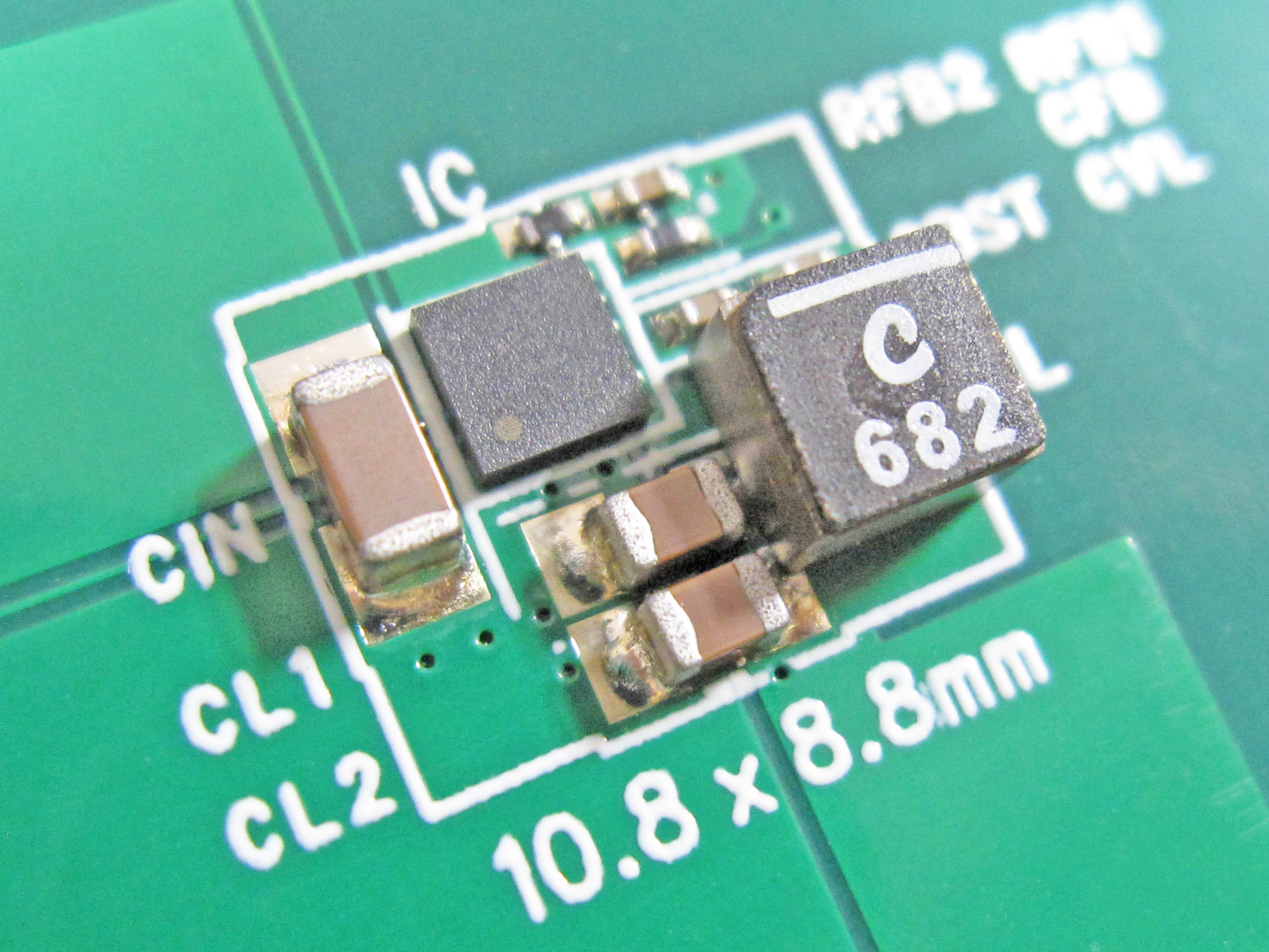
Click image to enlarge
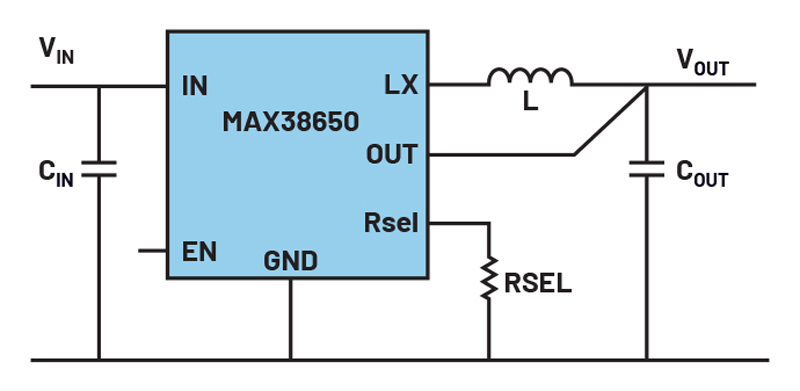
Figure 2: Nanopower voltage conversion for battery-powered sensors
Figure 2 shows an example of a voltage conversion circuit with the MAX38650. It is a 100mA nanopower step-down switching regulator. It can be operated with up to 5.5V supply voltage on the input side and can supply a regulated output voltage of between 1.2V and 5V. During operation, the switching regulator only draws 390nA of current itself (typical value). This is a very low quiescent current. When the switching regulator is off, it draws a mere 5nA. Sensor data is not acquired continuously, and communication is only necessary in the event of a fault. This means that the MAX38650 can often be switched to power-saving mode for additional energy savings.
Every basic voltage conversion circuit normally has a feedback pin. A simple resistor voltage divider is needed for the provision of a regulated output voltage. However, a resistor voltage divider doesn’t make much sense in an energy-saving circuit. Depending on the resistor values, either the current flow through the voltage divider is too high and leads to high losses or the resistor values are so high that the feedback node has a very high impedance. As a result, noise can couple into the feedback node and directly affect the regulation of the required voltage. Interference is especially a problem in industrial plants. As shown in Figure 2, the MAX38650 has an RSEL pin. It works with a single resistor, which sets the output voltage. When the MAX38650 is switched on, 200µA of current is briefly passed through the external resistor. A resultant voltage sets the required output voltage for the entire operating duration of the voltage converter. This is the best of both worlds: a low leakage current during operation and an adjustable, robust output voltage.
Dealing with Extremely Small Signals
Many sensors can measure extremely small signals. A very low noise power supply must be used to prevent these signals from being distorted. Conducted and radiated interference sources play major roles. While conducted interference can be greatly reduced with the help of additional filter circuits on the input side and the output side of the switched-mode power supply switching regulator, this is not quite that easy for radiated signal sources. A good board layout can protect against excessive interference radiation. Even then, residual noise coupling still exists in the system. This can only be reduced with good shielding, that is, a metal enclosure. However, such a shield is time-consuming to manufacture as well as cost-intensive.
A switching regulator employing Silent Switcher technology provides a very clever solution for minimising the radiated interference. Pulsed current paths that occur in any switched-mode power supply are designed symmetrically so that the magnetic fields that arise largely cancel each other out. This technology, in combination with flip chip technology, which eliminates bonding wires in the switching regulator IC, dramatically reduces radiated interference.
Up to a 40dB reduction in radiated interference is possible. This corresponds to a reduction in radiated power by a factor of ten thousand.
Figure 3 shows the symmetrical design of the Silent Switcher technology, with the simultaneously arising local pulsed currents shown in green. The pulsed currents generate pulsed magnetic fields with different polarities and cancel each other out for the most part.
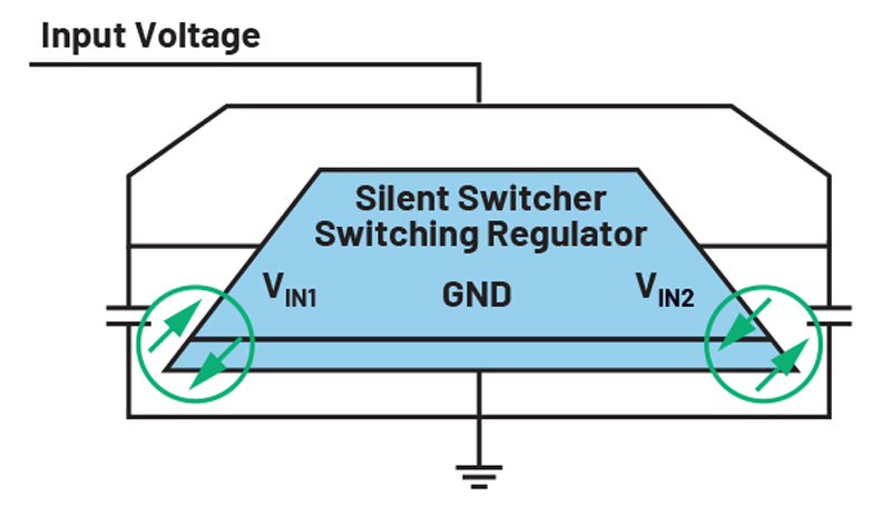
Click image to enlarge
Figure 3: Minimal radiated interference due to Silent Switcher technology
The Silent Switcher technology is now in its third generation. In this generation, a special ultralow noise technology is also employed in ultra-low noise linear regulators to reduce interference in the low frequency range, especially between 10Hz and 100kHz. This generation of Silent Switcher technology makes it possible in many applications to omit a filtering linear regulator between the switched-mode power supply switching regulator and the sensitive load.
When Size Plays a Key Role
Some sensors need to be positioned in very tight spaces - especially when an existing sensor should be replaced with a modern Intelligent Edge sensor in the same spot. Due to enhanced functionality, more electrical components are often also needed. As a result, innovative ways of reducing physical size must be found.
An interesting example from the voltage conversion world is the single-inductor, multiple-outlet (SIMO), which enables several different output voltages to be generated with a single inductor. The board space that would otherwise be taken up by multiple inductors can be saved with this.
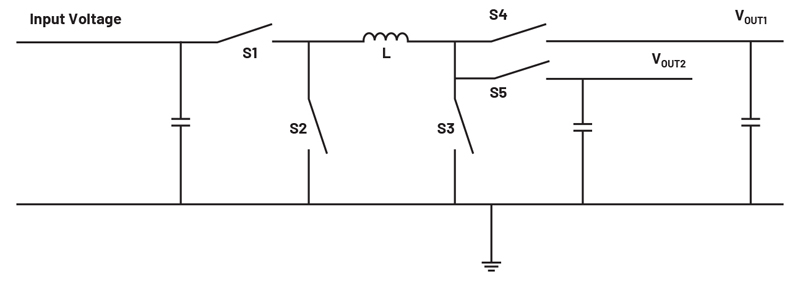
Click image to enlarge
Figure 4: SIMO power supply for use in extremely small sensors
Figure 4 shows an example of a simple SIMO regulator circuit for two precisely regulated output voltages. Additional supply voltages can be easily generated. Only one inductor, L, is needed.
The SIMO technology can be implemented as follows: The single inductor is used successively for all individual output voltages. A certain amount of energy is placed in the inductor and then used to generate the voltage VOUT1. After that, another defined amount of energy is placed in the inductor and used to generate the voltage VOUT2. In this way, each generated voltage gets exactly the amount of energy needed to keep it stable.