press x to close
Author:
By: Carlos Farnos, Dr.-Ing. Efrain Bernal / Editor: Gerhard Stelzer, Würth Elektronik eiSos GmbH & Co. KG
Date
09/28/2024
 PDF
PDF

Figure 1a here
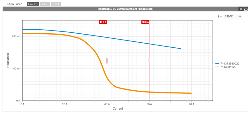
Figure 1a: Saturation current (Isat) comparison between a hard saturation ferrite power inductor (orange color) and soft saturation powdered alloy power inductor (blue color) at different ambient temperatures displayed by REDEXPERT. Saturation at an ambient temperature of 20ºC
Higher power requirements and miniaturization expose passives to rising temperatures, increasing the probability of thermal aging. This article explores how to select molded high-current power inductors, which are exposed to high temperatures for an extended time.
The constant market demand to increase power density and efficiency, as well as shrinking the power supply electronics, has pushed each element inside the system to its limits. Moreover, greater power requirements and miniaturization expose passive electronic components to higher and higher temperatures, increasing the probability of the thermal aging. This is a representative phenomenon that can be found in molded power inductors even with AEC-Q200 Grade 0 qualification (operating temperature range between - 55 °C to 150 °C). The following remarks will discuss the issues that inductors face when exposed to high temperatures for extended periods of time, with a special focus on molded high current power inductors and the necessity to recognize the effects of thermal aging in the inductor selection.
Molded Power Inductors
Many SMD power inductors use a technology called molding to press a magnetic metal alloy powder around the coil rather than use a discrete core. These inductors have superior magnetic shielding with low magnetic flux leakage, reduced potential for acoustic noise (high-pitched sounds when they are running), and a soft saturation roll off characteristic. Molded inductors are often more robust and reliable than other forms of power inductors, such as those assembled from two-piece cores or single piece cores (drum core) with epoxy resin coatings, making them well-suited for usage in harsh or demanding settings.
The powdered materials used in molded power inductors have minimal change in inductance with temperature and do not easily reach magnetic saturation. This is reflected in higher saturation current Isat specifications, making the inductor suitable for applications that require well-controlled inductance values at high currents and temperatures.
A new generation of power semiconductors based on SiC and GaN technologies have raised the requirements in terms of working frequency and power density. If traditional MOSFET technologies have been used in the range of 100 kHz to 500 kHz with some exceptions up to 1 MHz and power limited to 2 kW/m³, the new semiconductors are capable of operating at 10 times higher frequency (generally up to 10 MHz) at a power density up 10 kW/ m³ [1]. This places new demands on all the other power handling components, including inductors.
Characteristics of Molded Power Inductors
As the operating current and temperature increases, power inductors using ferrite cores become more susceptible to magnetic saturation resulting in system failure due to a sudden decrease in inductance. For this reason, designers use molded power inductors based on powdered magnetic alloy materials, to achieving more stable performance at high temperatures under high current operation, as shown in the Figure 1.
Click image to enlarge
Figure 1b: Saturation current (Isat) comparison between a hard saturation ferrite power inductor (orange color) and soft saturation powdered alloy power inductor (blue color) at different ambient temperatures displayed by REDEXPERT. Decrease of Q value at 2 MHz during 1000 h at 200°C
Molded power inductors must operate with minimum power losses to meet efficiency requirements of over 95 % with high-temperature stability (both in magnetic properties as well as in terms of long-term reliability).
Power losses in a magnetic component are split up into two types: core power losses and winding power losses. Winding losses are related to direct current (DC) resistance due to the bulk cross section of the conductor, and alternating current (AC) resistance in a conductor in the form of skin and proximity effect [3].
A high Rdc directly affects the I2R power loss and voltage drop due to the large DC current flow through the inductor coil. The low permeability of powdered magnetic alloy materials means the number of turns in the coil must be increased to obtain a desired inductance, increasing the length of wire which raises the Rdc.
Core power losses, on the other hand, are related to the material used to make the core of inductors; in this case, parameters such as geometric shape, volume, operating temperature range, operating frequency range, and magnetic saturation point must be taken into account [3].
Core losses mainly consist of hysteresis losses and eddy current losses. Hysteresis losses are related to the movement of magnetic domains within the material as the flux density
Many different magnetic materials are currently available on the market for inductor manufacturing that include traditional soft magnetic ferrites (Mn-Zn, Ni-Zn and Ni-Cu-Zn), soft magnetic metals (Si-Fe, amorphous, nanocrystalline) or powdered metal alloys (Fe-Si, Fe-Ni, Fe-Co). Though the base materials of metal alloy powdered cores have high permeability, their structure of isolated grains introduces a distributed nonmagnetic gap in the magnetic path, lowering their effective permeability, µe to less that 200 (generally 14-300). Ferrites and soft magnetic metals, both with high permeability (>1000) must be gapped when used for inductors. Inserting a gap into the magnetic path causes the hysteresis curve to tilt, reducing the effective permeability and therefore, requiring more magnetic force (current) to reach saturation. However, the gap's high magnetic resistance (reluctance) causes a field concentration in and around it which induces high eddy currents into nearby windings whereas distributed gaps do not.
As an alternative to ceramic materials with low saturation flux density, powdered magnetic alloys offer 2 to 3 times higher saturation flux density, and are available in many different material combinations for optimization to specific applications.
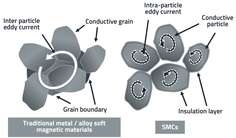
Powdered magnetic alloy particles are coated with a thin electric insulation layer and bonded together by a polymer or other material. The microstructure is illustrated in Figure 2. This type of magnetic core is called a soft magnetic composite (SMC).
Click image to enlarge
Figure 2: Typical microstructures and schematic eddy current paths of (left) traditional metal/alloy soft magnetic materials and (right) SMCs.[2]
The coated particles together with a binder are compacted under high pressure to form the core geometry. This distributed insulation layer separates the particles into many short unconnected electric paths to effectively reduce the eddy current losses. Additionally, the insulation coating and binder provide an even distributed gap along the magnetic path. Hence, SMC cores are suitable for high current and high frequency operation.
In an ideal scenario, there would be far less eddy current within a single particle than there would be if the particles were electrically conductive to one another within the core. This differs from ferrite cores which have a natural high material resistivity or from conductive soft magnetic metals which are made into insulated thin sheets or ribbons. For high frequency applications, this construction difference overcomes performance limitations of low permeability. Due to the distributed gap, SMC exhibits superior high DC bias handling, and exceptional temperature stability when compared to ferrite materials. These qualities make SMC a great choice for applications requiring high current and high-power density.
However, the expected long term temperature stability in molded power inductors is sometimes compromised when the component is exposed to high temperatures for long periods of time and used at high frequencies.
Here we focus on the degradation mechanism of the magnetic material, specifically on the deterioration of the insulation coating of powder particles in the inductor core and their relationship with the decrease of the inductor performances.
Thermal Aging
Thermal aging refers to long-term, irreversible changes in the structure, content, and morphology of soft magnetic composite cores. The degradation mechanism is triggered by the continued exposure at high temperatures over an extended period, which modifies the electrical insulation between the core particles. This results in substantially increased core losses, decreasing the inductor’s performance and its functionality in a SMPS application.
Some of the indicators of this undesirable phenomenon are higher power losses, increase of self-heating, increase of electromagnetic emissions (EMI), and decrease of the quality factor Q at high frequencies. Changes in the appearance of the core material are part of the observable phenomenon, that can also be related to the performance decrease.
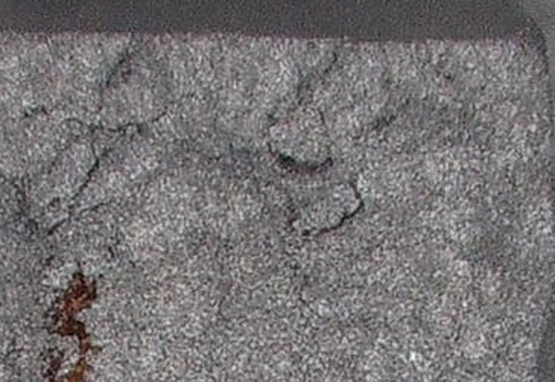
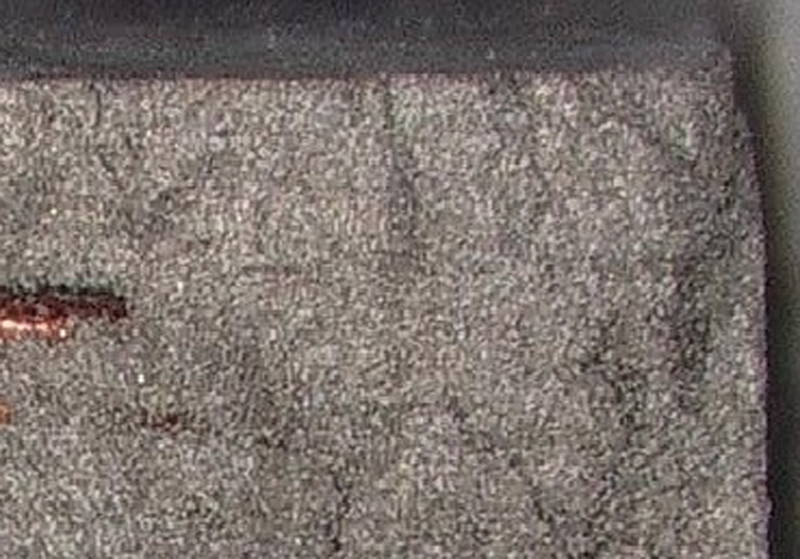
The magnitude of these changes is directly related to the core temperature, the exposure time and core material itself. To get a better understanding of the first effect of thermal aging, a test has been performed by comparing different molded power inductors at 200 °C for a period of 1000 h. Figure 3 shows how higher temperatures have a general effect on the material's appearance.
Click image to enlarge
Figure 3a: Higher temperatures have a general effect on the material's appearance, before test
Click image to enlarge
Figure 3b: Higher temperatures have a general effect on the material's appearance, after test
Over long periods of time, exposed at high temperatures, the insulation coating and binders of the iron powder begin to break down, reducing the resistivity of the material. Some manufacturers offer molded power inductors with AEC-Q200 qualification, however, there is a significant difference between a qualified inductor with and without a sturdy thermal aging improvement.
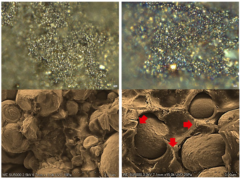
This is more evident, when the tested components are analyzed in more detail, as shown in Figure 4. The discoloration effect exhibited in Figure 3 is related to the burning of the inter-particle insulation of the materials and the merging of coating material. The results show that at higher temperatures, some components appear to permeate into the powder particles from the boundary, reducing the insulating barrier on the particle surface [8], and the tiny air gaps of the SMC material.
Click image to enlarge
Figure 4: The first row shows some burned areas after the test obtained with a microscope reference zoom at 1000X. The second row refers to scanning electron microscope (SEM) images and evidences a significant binder thickness reduction and the degradation, represented by the formation of secondary layers with seared materials.
Left column: before test; right column: after test
The results presented in Figure 3 and in Figure 4 reveal the impact of high temperatures on the core material even if the inductor is AEC-Q200 grade 0 (- 55 to +150°C) qualified.
As a designer, one must ask, why is this not detected during standardized testing during qualification? The main reason is that qualification tests are often based on the data sheet and the user’s general component specifications (i.e. environmental, etc.), which may not include power loss changes over time. Power inductors characteristics are often specified at 100 kHz, 100 mV/10 mA with and without DC bias. Normally this degradation phenomenon has little effect at this low frequency, but it is very significant in the MHz range. For this reason, according to the AEC-Q200 acceptance criteria the thermal aging effect is mostly undetected.
Thermal Aging Effect on Performance
When a molded power inductor is used for energy storage in a switching power supply, the effect of thermal aging is more prevalent at high voltages and frequencies.The larger the AC component of the inductor current is, the larger will be the proportion of the AC losses over the total losses. The increase of AC losses will generate extra heat to be dissipated into the ambient, which will translate into higher operating temperatures further potentially fueling this degradation process. This process carries the risk to turn into a catastrophic thermal runaway failure that compromises the complete system reliability.
When an inductor is used for EMI filtering purposes, the degradation due to thermal aging, in addition to AC losses increasing in the core, reduces the AC impedance of the inter particle connection in the powder affecting the impedance curve and reducing its effectiveness.
This degradation process can be monitored by measuring the Q value of the inductor over the time. Q is defined as the inductive reactance divided by the resistance at a given frequency (both Rdc and Rac resistance are taken into consideration). Therefore, the Q value is directly related to the power losses.
Test and Results
A test has been performed by using the new molded power inductors, WE-LHMI 7443732448100 and WE-LHMI 7443734948100 from Würth Elektronik [2], with an inductance value of 10 µH, against some popular competitors with similar size and inductance value. All the inductors under test, 100 samples in total, were exposed to a constant temperature of 200°C in a climatic chamber and periodically measured to monitor any change to the L and Q value, during the 1000-hour test. The selected inductors correspond to molded power inductors with a AEC-Q grade 0 qualification, and those with a grade 1 qualification but with a reported maximal operation temperature higher than 150°C.
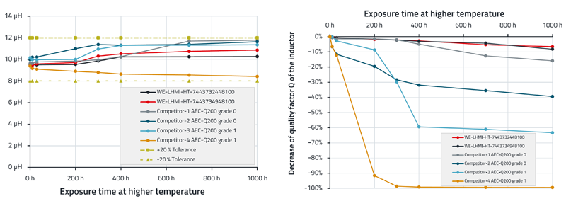
In Figure 5 (left), it is possible to trace that the reported inductance value of 10 µH stays between the ±20 % tolerance band, at the test conditions of 100 kHz (common for AECQ testing), during the 1000-hour test. This illustrates why it is not possible for designers to determine some changes in the performance by just measuring the inductance under typical test conditions reported in the datasheets. However, it can be seen that the quality factor Q decreases during prolonged exposure to higher temperatures as showed in Figure 5 (right). The figure presents the case of the quality factor Q obtained at a frequency of 2 MHz. Results show that, even for an inductor with the better AEC-Q200 qualification, the decrease can be significant, even though the measured inductance values were within tolerances.
Click image to enlarge
Figure 5: Performance comparison WE-LHMI HT version against competitors with AEC-Q200 qualification and reported temperature support more than 125°C.
Left: Inductance L value at 100 kHz during 1000 h at 200°C.
Right: Decrease of Q value at 2 MHz during 1000 h at 200°C.
Whereas the Q value is continuously decreasing over the time for some competitor‘s inductors, the tested WE-LHMI power molded inductors remain almost constant. Hence, for high temperature applications, the tested competitor’s inductors experience a constant decrease in efficiency and consequently increasing operating temperature compromising the long-term reliability of the system.
At a low frequency, there is no noticeable difference in Q value in concordance with the measured L value. However, the results of the test show a critical decrease of performance when the molded power inductor is used at frequencies higher than 100 kHz.
Würth Elektronik measures AC-losses with a triangular ripple current, i.e. a rectangular wave voltage, similar to the real operating conditions of a SMPS. The higher harmonic content of short duty cycle rectangular waveforms makes it necessary to use an advanced inductor measurement system for measuring a power inductor‘s AC-losses. It is possible to observe an increase in AC losses from the high frequency harmonics of the waveform resulting in an increase in the component's self-heating.
Würth Elektronik offers a full range of power molded inductors as part of the extensive portfolio of electronic components that are suitable for a wide range of temperature and applications. The new generation of molded power inductor series are available with different characteristics [2].
Designers have the possibility to select the right power molded inductor for their application within a huge range of sizes, performance, and structure. Targeting modern, demanding applications, the High Temperature WE-Molded Power Inductors Series offer a wide operating temperature from -55 °C to +150 °C with AEC-Q200 grade 0 qualification, with no thermal aging concerns.
This innovative solution ensures enhanced reliability and efficiency in demanding applications, aligning with the evolving needs of the industry for resilient and high-performance passive components.
Würth Elektronik eiSos GmbH & Co. KG
References
[1] Kasper, Matthias J., et al. "Next Generation GaN-based Architectures: From 240W USB-C Adapters to 11kW EV On-Board Chargers with Ultra-high Power Density and Wide Output Voltage Range." PCIM Europe 2022; International Exhibition and Conference for Power Electronics, Intelligent Motion, Renewable Energy and Energy Management. VDE. (2022)
[2] SMT Power Inductor WE-LHMI series from Würth Elektronik: www.we-online.com/de/components/products/WE-LHMI
[3] Farnós, C.; Bernal, E.: “Introduction to thermal aging in molded power inductors”, Application Note ANP128 from Würth Elektronik: www.we-online.com/ANP128