More efficient DC-DC Converters are moving the global automotive industry forward thanks to key increased demand and key industry trends
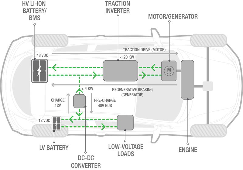
Figure 1: Simplified block diagram of a strong/full-hybrid EV
The global automotive DC-DC converter market is expected to be 18.7 billion by 2028 with a compound annual growth rate of 10%.[1]
DC-DC converters are an essential part of the vehicle, converting voltages to power various onboard systems, such as increasingly sophisticated infotainment and enhanced safety features using advanced driver-assistance systems (ADAS).
The growing adoption of electric vehicles (EVs), both battery-powered and hybrid EVs (HEVs), is also boosting the demand for DC-DC converters.
Let's examine some of the industry trends and technology that are helping to support the development of more efficient DC-DC converters.
HEVs and EVs have multiple architectural variations. Figures 1 and 2 show simplified block diagrams of these architectures. A high voltage (HV) bus supplied by the large battery drives the electric powertrain for strong or parallel hybrid and pure EVs.
The DC-DC converter is a critical component in both architectures, converting the higher-voltage bus (MH - 48 V or EV / HEV - 100s of V) to the traditional 12 V power bus, which powers most electrical loads. Our discussion focuses on the simulation, design, debugging, validation, and manufacturing test of this DC-DC converter.
Click image to enlarge
Figure 2: Simplified block diagram of mild hybrid EV
How Industry Trends Affect EV Design and EV Tests for DC-DC Converters
Extreme downward cost pressure exists on design and testing across the DC-DC converter development life cycle. Most DC-DC converters are water-cooled with silicon-based (Si) power converter designs. The additional cooling design cost passes to the design and test engineers, requiring reservoirs, pumps, and hoses to cool the DC-DC converter during design and test.
Consequently, manufacturers are minimizing the number of liquid-cooled modules by integrating multiple power converter applications into a single module (e.g., DC-DC converter and onboard charger). Additionally, designers are beginning to adopt new power semiconductor technology using wide bandgap (WBG) devices. Two leading technologies, Silicon Carbide (SiC) and Gallium Nitride (GaN), offer some significant advantages over Si.
Power efficiency
The ability of WBG devices to switch much faster than Si minimizes much of the power losses (switching losses) that occur during power conversion. Additionally, higher frequency means smaller magnetic components, supporting a less costly design.
High voltage operation
WBG devices handle much higher voltages (600 V and higher) than Si-based devices. This capability enables an HV bus architecture to power HEV / EV components with less current (i.e., small diameter wires), reducing the weight of wire harnesses.
High-temperature operation
The thermal conductivity and melting point of WBG devices enable it to operate at temperatures over 300°C. The ability to work at high temperatures provides a more reliable solution for HEV / EV applications that require high-temperature operation.
Simulation of a wide bandgap design
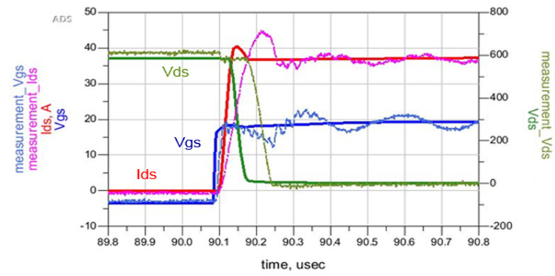
The emergence of WBG devices in power converter design complicates the simulation and design of the DC-DC converter. Manufacturers of GaN and SiC devices are still getting their processes in control and, therefore, do not have extensive device characterization. Users must evaluate each device to decide if the WBG devices will work in their designs. Additionally, because of the fast-switching characteristics, conventional lumped analysis simulators do not provide accurate simulations of WBG power converter designs (see Figure 3).
Click image to enlarge
Figure 3a: Conventional model & 3b: Simulation results – Source: Rohm Semiconductor
The conventional model / simulation shows a significant difference between simulated results (bold line) and measured results (faint line) when switching the power transistor on and off. The poor simulation creates costly design delays as designers iterate their designs, hoping the next prototype will work as expected. Having dependable simulations can also help improve the reliability of the DC-DC converter designs.
Bidirectional test
As more DC-DC converters become bidirectional, testing both directions of power flow requires test equipment capable of sourcing and sinking power to the DC-DC converter. Engineers traditionally do this by connecting a power supply and an electronic load in parallel. However, external circuitry (i.e. diode to stop current flow into the power supply) and cumbersome two-instrument programming, typically do not allow for smooth signal transitions between sourcing and sinking power. This setup will generate an inaccurate simulation of the operating conditions.
Electronic loads typically dissipate the power transferred to them from the DC-DC converter. However, the dissipated power (heat) can accumulate, especially for test applications where multiple DC-DC converters are testing in parallel. Due to the requirement of dissipating heat from electronic loads, these systems are often large, using forced air via fans or even water cooling.
Untested reliability and safety concerns
With new power semiconductor technology in many of the DC-DC converter designs, engineers must conduct additional design validation and reliability testing to ensure a reliable product will last over time due to harsh automotive operating conditions. Of course, the extra cost for the validation and reliability testing is necessary, even though these costs make the HEV / EV less competitive. The risk is high for skimping on tests if there is a quality problem with the DC-DC converters producing a HEV / EV.
Designers, technicians, and operators must exercise caution when testing a converter because of the power and voltage levels involved in DC-DC converters. The HEV/EV DC-DC converter exceeds the safety limit of 60 V, necessitating the implementation of specific safety mechanisms, such as NFPA 79, during manufacturing.
These safety standards require a redundant system, where one test system failure would not expose the high voltage to an operator. The redundant safety systems are often custom-designed, using programmable logic controller logic to operate independently from the test system. This approach adds extra design, cost, and complexity to the manufacturing test systems.
Maximize efficiency
The designer must maximize the efficiency of their converters. Efficiency depends on many factors, including temperature, operating voltage, percentage of rated power, and other environmental conditions. Because of the numerous influences on efficiency, it is difficult for the designer to simulate all the combinations of conditions to characterize their design. Additionally, measuring 0.1% changes in efficiency at 95% efficiency or greater requires a measurement instrument with a high dynamic range, typically 16 bits or better resolution. Combined with the need for accurate, current transducers and well-synchronized current and voltage waveforms, the measurement challenges are complex.
These efforts should also include the whole system operation of the electric powertrain to maximize efficiency. As the industry develops more efficient control algorithms for different combinations of internal combustion engines and motor-powered propulsion and regeneration, the DC-DC converter will play a part in routing power. Power hardware-in-the-loop testing is crucial for real-world testing of the whole system's efficiency as it validates DC-DC converter’s firmware and the control algorithms spread across the power train components.
Emerging Solutions
The auto industry is developing new, innovative approaches to address some of these design and test challenges for EV design and testing of DC-DC converters.
High-Frequency Enabled models / simulations
Because of the higher frequency content of WBG switching waveforms with rise and fall times < 10 ns, engineers must use high-frequency or electromagnetic-enabled models and simulators to simulate power semiconductor behaviors accurately. Engineers must use electromagnetic interference (EMI) simulation to understand the DC-DC converter's contribution to radiated and conducted interference.
Engineers must also consider the physical positioning of the parts in the converter's layout, the characteristics of semiconductor package parasitics, and printed circuited board effects. Furthermore, thermal simulation and analysis are critical to understanding cooling requirements with the significant impact of temperature in DC-DC converter designs.
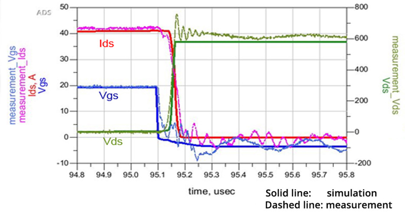
A semiconductor engineer can use an empirical / mathematical model incorporating high-frequency characteristics (S parameters measurements for ‘zero bias’ and on-state for the switching transistor model) and electronic design automation software to simulate their devices in converter designs. They are able to achieve significant improvement in matching simulated data with measured data using this technique (see Figure 4).
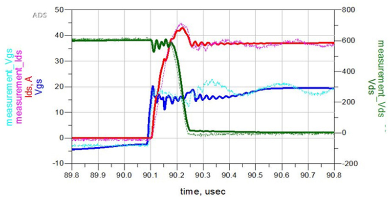
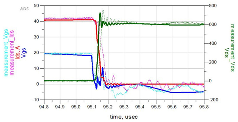
Click image to enlarge
Figure 4a: Conventional model & 4b: Simulation results
Multiple vendors are introducing integrated source / sink solutions in a single product. The products can seamlessly move from sourcing current (Quadrant I) to sinking current (Quadrant II) without external circuits or synchronized programming of a separate power supply and electronic load (see Figure 5). The integration enables a smooth output waveform that correctly simulates the bidirectional DC-DC converter's transition between opposite directions of power flow.
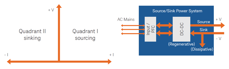
Click image to enlarge
Figure 5: Source/sink power system
When the power system sources power to the DC-DC converter, most of the power (depending on the efficiency) passes through the converter to the automotive load. When the power system sinks power from the DC-DC converter, the power system must absorb the power. Most power systems or electronic loads dissipate this power in heat, requiring larger-size products with fans for power levels of DC-DC converters of up to 4 kW. Consequently, increasing the test system size and HVAC requirements is necessary to remove the heat from the facility.
At the 5 kW power level and above, there are source/sink power systems and electronic loads that regenerate (or return) the power to the AC mains (see Figure 5). While this technique may not achieve 100% efficiency, most designs allow approximately 90% of the power to return to the grid. Consequently, only 10% of the power, or approximately 500 W in the case of a 5-kW product, needs to dissipate as heat. The result is a dramatic reduction in the size of the products and the HVAC cost to remove heat from the test system environment.
The critical question for regenerative solutions is, how clean is the power returned to the AC mains?
If you work in manufacturing, test systems in the facility amplify any distortion in power returned to the AC mains. Dirty power can create intermittent problems in your facility, requiring isolation transformers for each test system to help mitigate the problem created by poor regeneration. It is best to check with the product vendor to confirm low distortion power returns to the AC mains (see Figure 6).
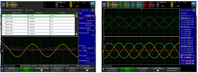
Click image to enlarge
Figure 6: Total harmonic distortion and power factor measurements on power returned to AC mains from a regenerative power system; measurements made with a power analyzer
Summary
Designing and testing DC-DC converters continue to be a challenge as the functionality of these modules evolves with the market. Cost pressures are significant in this market and will persist. New technologies like higher capacity lithium-ion batteries and wide bandgap power semiconductors are the enablers to help this market breakthrough into the mainstream. The thoughtful adoption of new design and test technologies and approaches is necessary to enable engineers to maintain the quality and reliability of the DC-DC converter while minimizing unnecessary costs.
[1] Automotive DC-DC Converter Market Size & Share Analysis - Growth Trends & Forecasts (2023 - 2028) Source; Mordor Intelligence