Robotics system demonstrator for Infineon power electronics devices
Figure 1: Fully assembled IMR and the exploded view
Mobile robots are now commonly found in commercial and industrial applications. On a high level, they can be categorized into two main types:
- Automated Guided Vehicle (AGV): moves along predefined marked paths (e.g., wires, magnetic tapes, lasers/barcodes), guided by external means, and not fully autonomous.
- Autonomous Mobile Robot (AMR): moves fully autonomously without external guides. Using built-in sensors, the robot can map its environment, determine its position accurately, and avoid obstacles. Additionally, it can recognize the encountered objects and interact with humans.
Infineon Mobile Robot (IMR) (Figure 1) is a system demonstrator designed as an AMR equipped with several sensors to be fully autonomous. Additionally, it has actuators with smart and efficient motor control, robust power distribution, and reliable battery management system (BMS) solutions.
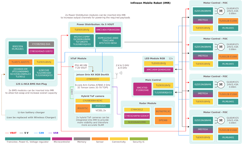
IMR’s system architecture (Figure 2) describes that IMR is driven by motors in all four wheels, equipped with two hot-swappable BMS modules, and two power distributors designed with an interleaved buck converter to minimize the current ripples in the system. For autonomous navigation, a hybrid-Time-of-Flight (hToF) camera is used. It consists of a sunlight-robust REAL3™ 3D image sensor, and two IR transmitters driven by Infineon VCSEL drivers for spot and flood illumination, enabling both mapping and obstacle-avoidance tasks with just one device. For wireless communication, IMR has the latest 3-band 2x2 Multi-User-MIMO Wi-Fi 6/6E (802.11ax) and dual-mode Bluetooth® module, based on the Infineon CYW55573 chipset. This enables data rates of up to 1.2 Gbps with Wi-Fi in the 5/6 GHz band and up to 3 Mbps with Bluetooth®.
Click image to enlarge
Figure 2: IMR system architecture
Smart and efficient motor control solution
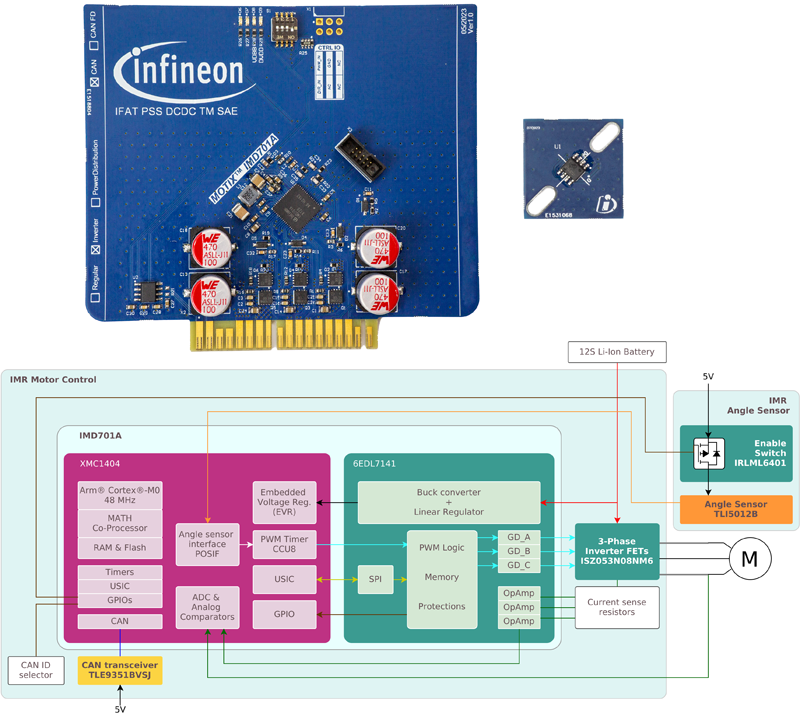
IMR’s motor control solution (Figure 3) uses very compact power electronics devices, namely MOTIX™ IMD701A-Q064X128, that integrates an XMC1404 Arm® Cortex®-M0 microcontroller and a programmable MOTIX™ 6EDL7141 three-phase gate driver, and OptiMOS™ ISZ053N08NM6 80 V power MOSFET in PQFN 3.3x3.3 package.
XMC1404 includes a MATH co-processor running at 96 MHz, providing a 32-bit divider and a 24-bit CORDIC for trigonometric calculations executed in parallel with CPU operations. This means that the calculation time for a division operation is reduced significantly and the increased computational power allows the use of XMC1404 for real-time critical tasks. Additionally, a field-oriented control (FOC) algorithm can be implemented in high resolution.
6EDL7141 provides maximum flexibility and safety in designing three-phase BLDC motor drives. It provides a configurable MOSFET switching slew rate, which in turn minimizes interference (EMI) and improves system efficiency due to dead-time optimization and reduced switching losses. The integration of a synchronous buck converter and an LDO regulator that can be used to power external components, high/low-side charge pumps, and three current sense amplifiers with adjustable gain and offset, reduces the BOM and PCB footprints significantly, along with simplifying PCB design.
ISZ053N08NM6 is built with the latest Infineon OptiMOS™ 6 MOSFET technology exhibiting 29 percent reduction of on-resistance (RDS(on)) and 38 percent reduction in the figure-of-merit from the previous technology and thus, further reducing the system losses significantly.
Click image to enlarge
Figure 3: IMR motor control solution including the position sensor and its simplified block diagram
The integration and the use of the above-mentioned devices offer the motor drive system the benefits of a simplified design, high power density and efficiency, fast control loop, EMI minimization, and high performance-to-price ratio. Additionally, the motor control system’s functionality is enhanced by the inclusion of TLE9351BVSJ, which is a high-speed CAN transceiver supporting up to 5 Mbit/s data rate and equipped with VIO input to be flexible in interfacing with either a 3.3 V or 5 V MCU.
IMR’s motor control solution is a turn-key solution with FOC and CAN communication firmware included at no additional cost for easy parameter-optimization and modification. It is designed to work with the magnetic-based position angle-sensor TLI5012B-E1000 that provides both the rotor position in the motor and the rotational speed of the motor for the robot’s control. Using this sensor, a direct-drive motor can be used to reduce the motor space requirement in the robot. Additionally, the angle sensor enables a more accurate torque control and a much smoother initial start, allowing the robot to operate at a very low rotational speed without cogging, minimize vibrations, and achieve higher system efficiency and stability.
Smart and reliable BMS solution
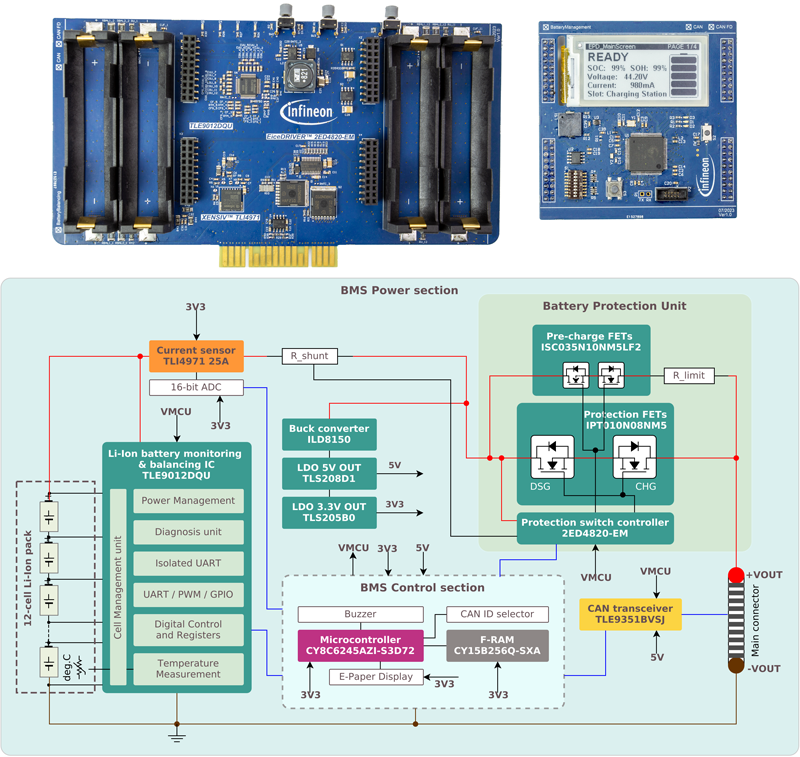
The IMR BMS solution (Figure 4and Figure 5) is a complete, stand-alone battery-pack solution consisting of the power and control sections. The power board features the highly reliable BMS IC TLE9012DQU, which is capable of balancing individual Li-Ion battery cells (up to 12 cells in series) and providing high-resolution measurement of each cell voltage. It also provides five-channel temperature measurements, enabling a highly accurate calculation of the state of charge (SoC) and the state of health (SoH). Additionally, it is equipped with a cell diagnostic unit to detect open-load and open-wire connections, and balancing overcurrent and undercurrent events. Finally, it has a differential serial UART interface ensuring robust data communication with the host MCU.
Click image to enlarge
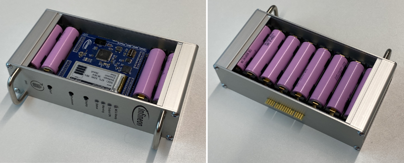
Figure 4: Fully assembled BMS module solution of IMR (front and back view)
Click image to enlarge
Figure 5: Simplified block diagram of IMR’s BMS solution showing both the power and the control board
Equally important is the presence of the protection unit in the power section that consists of the two-channel gate driver, protection switches, and pre-charge switches, which are used to control the inrush current between the battery and the load. EiceDRIVER™ 2ED4820-EM is a smart high-side n-channel MOSFET gate driver with two independent outputs supporting the back-to-back MOSFET configuration. It is integrated with a charge pump and a current sense amplifier and equipped with a serial interface (SPI) to adjust and read parameters available in the registers, such as overcurrent-detection threshold and amplifier gain. In this solution, a common-source back-to-back MOSFET topology has been selected to allow simultaneous control of both protection and pre-charge switches.
As pre-charge switches, the OptiMOS™ 5 ISC035N10NM5LF2 100 V power MOSFET stands out due to its wide safe-operating-area (SOA) combined with the very low RDS(on) in the SSO8 5x6 package. It is also generally well suited to be used for protection switches during battery charging and discharging. Nevertheless, to ensure maximum safety and reliability, another power MOSFET, OptiMOS™ 5 IPT010N08NM5 is used for the protection switches instead. This is because it can handle more than double the current load, thanks to its lower RDS(on) and larger package, to anticipate the large discharge peak-current and the large transient-current during hot-swapping.
Intelligent BMS control can be performed via the on-board MCU, PSoC™ CY8C6245AZI-S3D72, which has two cores – an Arm® Cortex®-M4F running up to 150 MHz and an Arm® Cortex®-M0+ running up to 100 MHz, and 512-kB application flash. Provisioning for reliable and fast data-logging of the cells’ measurements and other data, an additional non-volatile F-RAM CY15B256Q-SXA having a density of 256 kbit is included in the design. This solution is equipped with the same high-speed CAN transceiver to allow the module to participate in the CAN communication within IMR.
Similar to the motor control setup, IMR’s BMS is a turn-key solution featuring control firmware with CAN communication at no additional cost. SoC and SoH estimation of the battery pack, and hot-swapping control are included in the firmware. Programmers also have the full freedom to implement their own control and algorithms, thanks to the on-board MCU. The BMS solution offers system benefits of compact design, hot-swapping capability with highly reliable components, highly accurate measurements, high flexibility and compatibility with 3.3 V or 5 V microcontrollers, and an intelligent BMS solution.
Summary
IMR has been designed as a system testbed of Infineon’s subsystem solutions, especially for power electronics. The integration of motor control, BMS, and power distribution solutions in addition to the navigational sensors and wireless connectivity validates the functionality and capability of each subsystem operating in the target application. Functionally, IMR demonstrates Infineon’s trustworthy system solutions in robotics and serves as a development platform for continual improvement and technological breakthroughs, as well as a testing ground for robotics designs. Experience the IMR’s capabilities in person, coming to a tradeshow near you soon!