Author:
Christian Jonglas, Customer Support Manager at GAIA Converter
Date
07/25/2024
 PDF
PDF
Click image to enlarge
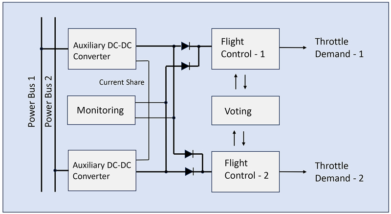
Figure 1: Redundant auxiliary DC-DC converters in an ‘on-line’ arrangement
Sci-fi movies have shown visions of the future where flying taxis buzz around with the hero pilot dodging skyscrapers and other aircraft. This is now set to become reality, at least in a less frantic way, with the prestigious 2023 Paris air show featuring a real flying demonstrator of a potential air taxi, the Volocopter as well as many other mock-ups from small start-ups to the biggest aerospace manufacturers. Although the air taxi of the movies usually seems to have some sort of anti-gravity drive, the ones we might travel in will be electrically powered, part of the upcoming eVTOL or electrical Vertical Take-Off and Land technology.
Of course, we have had helicopters as ‘taxis’ since the 1940s but with their gas turbine engines they are noisy, polluting and only for the super-rich. Small eVTOL aircraft are whisper quiet, potentially emissions-free and it has been said by German company Lilium that as taxis, they could eventually be cheaper to hire than a cab, maybe $2-$3 per kilometre.
The eVTOL passenger craft movement is clearly evolving from drone technology but there are big differences in commercial realization, not least of which is certification to carry passengers, particularly because it is a goal for eVTOL aircraft to be autonomous. It is such a new area that there are no clear routes for type approval and product certification, although the issue is being addressed by the European Aviation Safety Agency (EASA) and in the US by the FAA, where the indication is that certification could be on a case-by -case basis. Operationally, the craft need to fly in urban environments to make sense as taxis and might need designated ‘vertiports’ with all the obvious safety, infrastructure and environmental impact considerations.
eVTOL Craft Must Be Fault Tolerant
Despite the need for minimum weight and size, the control electronics in an eVTOL craft must have the same safeguards and fault tolerance as any traditional aircraft, and that means redundancy for critical systems. These would be motor and surface control, navigation and communication as a minimum. A measure of the reliability needed is ‘catastrophic failure rate’ and a value put to this by EASA is 10-9 per flying hour, sometimes expressed as its inverse, a mean time between failures (MTBF) of a billion hours. This might sound very conservative, but when the craft become common, for say 10,000 in service, it means that no more than one should catastrophically fail during 11 accumulated years’ flying, which should be far beyond a typical service life. Note that it is during the 11 years, not after – a constant failure rate during service life is assumed. For an individual craft, this corresponds to a probability of survival after 11 years flying of 0.99999, which sounds reassuring. A difficulty though is the determination of the failure rates for components, as calculation standards such as MIL-HDBK-217F and Telcordia SR-332 can differ markedly in their results.
How Much Redundancy?
Whatever calculation standard is used, electronics in an eVTOL craft cannot practically achieve a billion hour MTBF during service life without redundancy. However simple duplication of a system yields a huge improvement. If failures are repaired and the duplicated systems are both actively on-line with equal failure rates, the overall failure rate λT is given by:
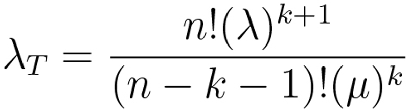
This for n systems each with λ failure rate (per hour) with a repair rate of µ (per hour) and with k systems minimum required to fly the craft.
To achieve a failure rate λT of 10-9 per flying hour, with 2 redundant systems such that only one is needed, with a repair time of three hours (µ=1/3), λ calculates to 1.3 x 10⁻⁵ failures/hr or an MTBF of 77kHrs, which is a realistic figure for a system.
Monitoring is Vital
The value for failure rate just calculated does depend on immediate detection and timely rectification of failures. With active redundant systems, if there is seamless switch-over when one fails, the system effectively reverts to one with lower reliability, so an alarm must register the failure immediately. A problem though is detection of a ‘soft’ failure where one computer say, just gives a different command to the other in a redundant pair. If one says ‘nose up’ and the other ‘nose down’ which one is right? For this reason, it might be necessary to have at least three in a redundant set so the outputs can be ‘voted’ on’.
Although only a single main traction battery is realistic, auxiliary power rails generated from DC-DC converters with their inherent high internal stress levels and temperatures should also be duplicated for redundancy. Precautions must be taken such that one failing should not cause another to also collapse. Monitoring is more straightforward though, as output voltages are generally predetermined and unchanging.
Configuring Redundant Auxiliary Power Rails
There are some choices when configuring redundant auxiliary power rails. The arrangement could be ‘on-line’ for example, with two DC-DCs continuously operating, sharing the power and with outputs gated together though isolating diodes (Figure 1). The arrangement has the advantage that both units can be continuously monitored for health, giving certainty of continued functionality after a single failure. The monitoring must also be independent, and any current share control must not introduce a single point of failure. The gating diodes or sometimes MOSFETs must also be carefully chosen and included in the monitoring, as a shorted diode, for example, may allow ‘normal’ function, but if its driving DC-DC fails with an output short itself, the gated power rail will be dragged down. Each DC-DC must be capable of supplying the full load and any transients, which does mean that in normal operation they will operate at low stress with a consequent boost to reliability.
The system of Figure 1 could operate without the gating diodes and power monitoring if it is accepted that one DC-DC failing can disable a complete flight control channel. Whether this gives an overall benefit in system reliability will depend on the actual failure rates of the DC-DCs and their loads. It is subjective, but perhaps likely that a pilot would rather have two flight control computers fully operational with one DC-DC failed, even if it means inclusion of a few unstressed monitoring and power sharing components.
Off-Line Back-up is an Option
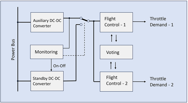
An alternative is an off-line arrangement where one DC-DC is off or idling and is physically switched-in if the primary DC-DC fails (Figure 2). This is potentially a simpler arrangement without the components needed for gating and current sharing. However, the main DC-DC supplies the full load and is more highly stressed than in an on-line arrangement, increasing its failure rate. This is offset by a system increase in reliability due to the off-line DC-DC not ‘using up’ any of its lifetime in normal operation. Whether on- or off-line configurations give an overall improvement in system reliability will depend on the application detail. A disadvantage of off-line operation with an un-powered back-up is that you must believe that it will power on when required in an emergency. To ensure this, the switch-over to the second DC-DC would need to be exercised regularly and perhaps the primary and secondary DC-DCs routinely swapped over to equalize their remaining lifetimes. Any delay in reacting may also risk a dip in output voltage. This could require additional hold-up measures such as a large parallel capacitor, which itself will add significantly to the failure rate calculation. Perhaps most problematic is that any changeover switch is a single point of failure – if mechanical, it will naturally have a high inherent failure rate. If electronic, it will introduce losses and need careful design to achieve an extremely low failure rate.
Click image to enlarge
Figure 2: Redundant DC-DCs in an ‘off-line’ arrangement
Practical Implementation
The main battery for the rotors will be at relatively high voltage, similar to an EV, to keep current manageable at the high power levels involved. This means that an intermediate bus voltage is likely, perhaps at 24V or 28VDC, generated from high power DC-DC converters gated for redundancy. This voltage might be used for ancillary power systems such as lighting, actuators and smaller motors so could be relatively noisy, and avionics/military standards for power quality could apply such as MIL-Standards 1275, 704, 461 and DO-160. Further converters, probably with isolation, would generate yet-lower, clean voltages for distribution around circuit boards. A typical system might look like Figure 3.
Click image to enlarge
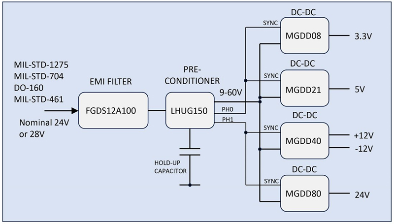
Figure 3: Outline of a power distribution system in an eVTOL application
Here a monolithic EMI filter from Gaia Converter attenuates fast transients and noise in both directions on a 24/28VDC bus while a pre-conditioner module from Gaia from their LHUG series handles slower surges and dips according to the power quality standards. It also includes reverse polarity protection, inrush control and soft start. An additional feature is an active hold-up mode where in normal operation, an external capacitor is charged to a high voltage, irrespective of input. This is switched in after a power drop to give extended holdup with a relatively small capacitance value.
The downstream DC-DCs shown are from Gaia with various ratings up to 80W in this instance and can be synchronized with each other and to the pre-conditioner module. Two synchronization phases are available to minimize input ripple current and noise generated. All parts have remote sense, voltage trim, an ON-OFF function, and secure protection features including output over-voltage and over-current, over-temperature and input under-voltage. The DC-DCs from Gaia described are avionics grade, encapsulated, PCB-mounted and with temperature ratings to 105°C to suit the environment, with options for cold-wall cooling.