
Brushless DC motor drive circuitry is complex, as is associated control, sensing and feedback. This article examines the technique of Field Oriented Control...
Figure 1: BLDC motor six-step trapezoidal compared with sinusoidal drive waveforms
There are many types of motors with their own pros and cons, but brushless DC (BLDC) types have become ubiquitous for their excellent efficiency, high performance, long life and low electrical and audible noise. If they have a downside, it is the relative complexity of the electrical drive, usually requiring three-phase 120 degree-shifted AC power at high frequency, with pulse-width modulation (PWM) to generate the demanded speed and torque.
The potential controllability, efficiency and weight savings from the use of BLDCs has however driven the development of new integrated drive solutions that have opened up markets ranging from industry to domestic appliances and new applications such as in drones and E-bikes.
BLDC motor basics
All common motors work by the interaction of magnetic fields. In the case of BLDCs, a rotating field produced by sequentially energizing the three stator windings acts on the static magnetic field of the permanent magnet in the rotor, ‘dragging’ it round. With a simplistic ‘on-off’ excitation to each stator winding, drive implementation is relatively easy. However, the force on the rotor is not constantly in the desired tangential direction – a periodic radial component is present as the motor rotates which does not contribute to shaft torque and serves only to reduce efficiency, produce heating and induce so-called ‘torque ripple’ (Figure 1, left). This simple drive is called six-step or ‘trapezoidal’. The ideal situation is to use a sinewave rather than on-off drive to the windings, (Figure 1, right), to produce a smoothly rotating field from the stator coils and then control the AC excitation current such that angle of the resulting field is always perpendicular to the field of the rotor magnet.
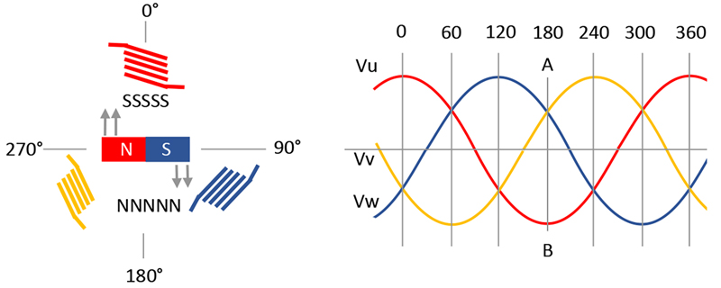
This maximizes tangential force and hence torque around all 360 degrees of rotation, resulting in minimal torque ripple and maximum efficiency. To achieve this, the rotor angular position much be accurately known and the stator currents controlled, which themselves produce the particular field intensity and direction at any instant, from the overall contribution of the three windings. Figure 2 shows an example – with the rotor in this position, with its field in the direction N-S, the magnet experiences maximum torque overall if the stator field direction is at 90 degrees, in the direction of the double gray arrows. This occurs when fields from the W and V windings are equal in one polarity and the field from the U winding is maximum in the other polarity corresponding to position A-B in the drive current waveforms.
Click image to enlarge
Figure 2: Rotor torque should be tangential for maximum effect
Applying and controlling just sinusoidal voltages to the three windings in the correct phase will not give accurate control, as winding inductance, back EMF and other effects cause a phase shift to the resulting current and field. This is where Field Oriented Control (FOC) comes in, dynamically correcting stator field amplitude and direction by controlling measured winding currents to be optimum for the instantaneous measured rotor position.
Field oriented control is optimum to maximize torque
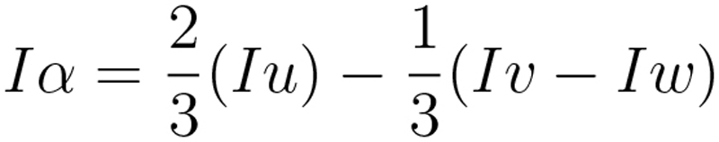
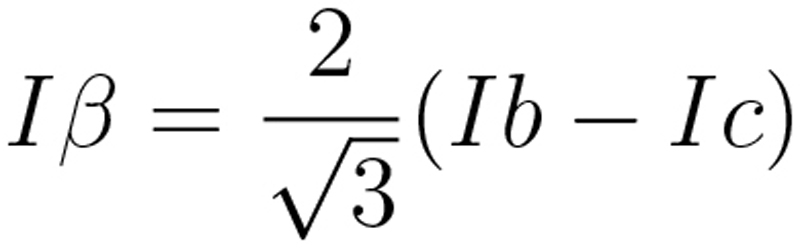
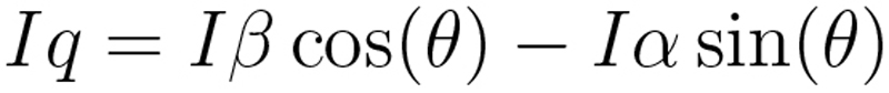
Stator winding currents and consequent field intensity and direction can be represented as three rotating vectors 120 degrees apart, in a common static frame. If the currents IU, IVand IWare always balanced, adding to zero, this can be simplified into two rotating vectors amplitude Iαand Iβ, 90 degrees apart in a static frame, by the ‘Clarke’ transformation:
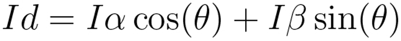
We now need to convert these vectors into static ones ID(direct) and IQ (quadrature) in a rotating reference plane so we can correlate them with the position of the rotor as this revolves and this is done using the ‘Park’ transformation, where θ is the rotor angle around the static Iα and Iβ frame:
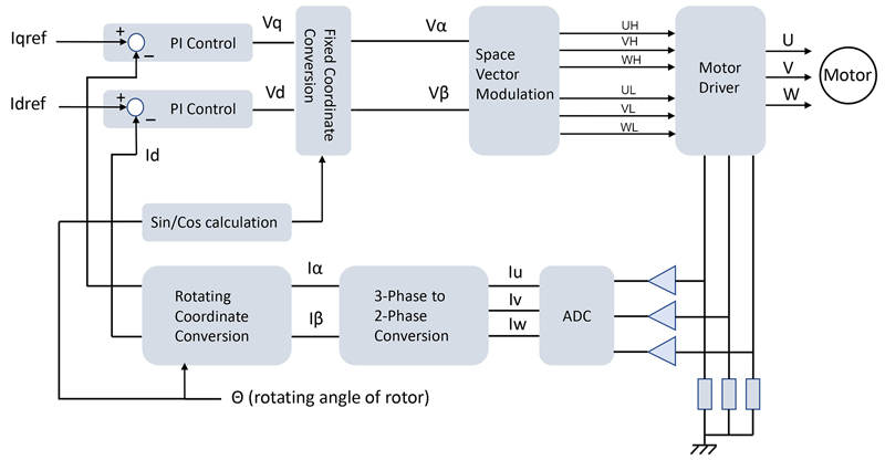
Under steady state conditions, ID and IQ are constant valuesand can be interpreted as the components of stator winding current that represent tangential torque and unwanted radial torque, respectively. These values can now be used as inputs to feedback loops, typically using proportional-integral (PI) controllers, that work to maximize IQand minimize IDto zero. The resulting error amplifier outputs VD and VQ are passed through inverse Park and inverse Clarke transformations with subsequent pulse width modulation, to drive a power stage, generating the three sinusoidal stator winding currents. The programmable gain values in a PI controller, Kp and Ki, need to be separately optimized for transient response and steady state accuracy respectively and are heavily dependent on actual motor parameters, particularly winding resistance and inductance. However, advanced FOC controllers such as those from Qorvo, have auto-tuning features where they ‘learn’ the characteristics of the connected motor. An outline of a BLDC motor controller using FOC is shown in Figure 3.
Click image to enlarge
Figure 3: A typical BLDC motor controller using Field oriented Control
Applications that benefit particularly from FOC are where noise or vibration need to be minimized, low harmonic contact is desirable and those that need to run at higher than nominal speed. This is achieved in FOC with the technique of ‘field weakening’ where back-EMF is deliberately reduced by controlling current ID to be lower to a negative value, reducing the effective rotor magnetic field and allowing higher speed, but at the expense of torque.
Measuring rotor position and stator winding currents
High-performance FOC relies on accurate measurements of rotor angular position and stator winding currents. Position can be determined in various ways – with trapezoidal drive, one winding is unenergized at any instant and the zero crossings of the back-EMF present can be used to indicate position at low cost and with good accuracy. However, in FOC, all windings are continuously driven, so other methods are used. A ‘sensorless’ technique infers position from winding current, voltage and a model of the motor characteristics, but this does not allow easy start-up under high load and requires significant processing power from the controller. A possibility is to start with trapezoidal drive, sensing back-EMF, then to switch to sine FOC when the motor has spun-up. As one of possible sensor-based solutions, Hall sensors anyway solve this problem providing a simple interface and allowing start-up under high load conditions and more precise torque control. Other solutions to position measurement are a magnetic resolver or an encoder with quadrature outputs, which are more costly but highly accurate and also sense direction of rotation.
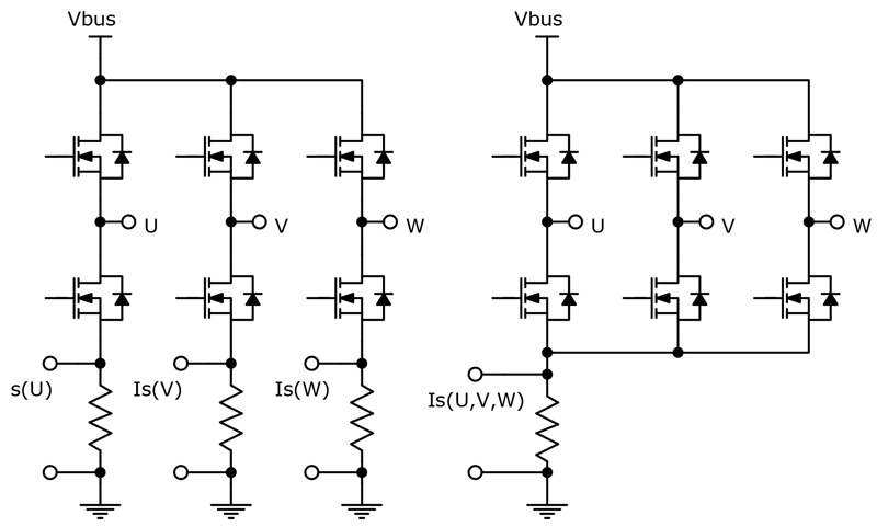
Measurement of winding current can also be done in different ways. The most accurate is to sample each of the three winding currents simultaneously with perhaps resistive sensing and three ADCs. However, timing of the sampling is critical to avoid noisy PWM switching edges. Resistors could be placed directly in series with the windings for ultimate accuracy but then measured voltages are not ground-referenced and are difficult to process with the high common-mode waveform levels present, so a better solution is to measure the inverter leg currents (Figure 4, left). For cost-sensitive applications, a single shunt resistor can be used, effectively measuring the DC-link current (Figure 4, right). Only one ADC is required for the single shunt approach, but the technique has limitations – the current measurement will not be accurate if the active vector duration is less than the minimum measurement time and to correct this, ‘asymmetrical’ current sampling might be necessary to provide better signal quality.
Click image to enlarge
Figure 4: BLDC motor current monitoring methods, three-shunt, left and single-shunt, right
Integrated solutions to BLDC FOC control
All of the functions for trapezoidal or field-oriented control of BLDC motors can be integrated into single-chip controllers, such as the PAC5xxx series from Qorvo, based on the ARM® Cortex® processor. The parts are highly configurable and cater for up to around 3 kHz electrical speed. Control modes include torque, speed and power, with ‘sensorless’, Hall or quadrature encoder position sensing options, while single or three shunt current sensing can be utilized. A hybrid trapezoidal/FOC mode is included for assured start-up, along with auto-tuning to identify motor parameters for optimum performance. Field weakening is supported and a range of protection features detect issues such as under-voltage, over-temperature, stall and open phases, reported through on-board diagnostics. One version even includes the motor driver MOSFETs for low power applications, such as hand-held devices and tools. All features can be configured through a GUI and comprehensive support is provided through reference firmware, application notes, programming guides, a software development kit and hardware evaluation kit.
Conclusion
Field oriented control of brushless DC motors is an optimum solution for highest electrical and mechanical performance. With the cost-effective, miniature, integrated controllers now available, this technique can be considered for all applications from heavy industry to the smallest of hand-held devices.


