Addressing the total solution and best practices for testing
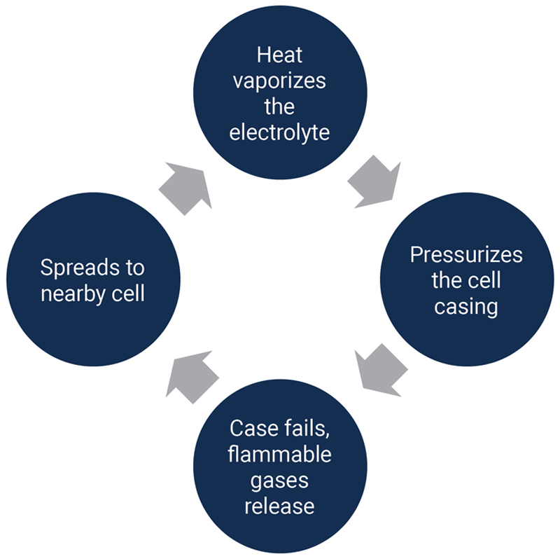
Figure 1: A thermal runaway cycle
Electric vehicle (EV) battery packs, by necessity, need to have a high capacity to power vehicles weighing well over a ton. To maximize driving distance between charges, battery packs for some vehicles have capacities as high as 100 kWh. Battery pack capacity will have to increase even further for larger vehicles such as trucks, earthmoving equipment, electric trains, and eventually electric airplanes.
Similarly, battery pack voltages are increasing from 400 V to 800 V and even higher to make the vehicles more efficient. Higher voltage allows the battery to drive the motors and other loads with lower current. Vehicles can use smaller, lighter cables to reduce vehicle weight. In addition, the lower current requirement results in less I2R power loss in the cables. The lighter weight and lower power loss in power cables maximize battery life for longer drive distances.
With both high power and high voltage in battery packs combined with highly reactive Lithium in Lithium-ion battery cells, ensuring EVs have safe battery packs requires 100% testing of all battery packs. Testing enables verification that a battery pack complies with its specifications. Of greater importance during testing is preventing thermal runaway, which will destroy a battery pack, can damage a facility, and endanger personnel. While Lithium-ion battery packs have superior energy density, the tradeoff is the potential for thermal runaway.
This article will present the causes of thermal runaway and recommend features that test facilities and test systems should have both for the safe testing of battery packs to avoid thermal runaway and for the protection of the test facility and the battery test system.
Causes of thermal runaway
Thermal runaway of Lithium-ion batteries is a self-sustaining condition in which an increase in temperature causes a further increase in temperature, leading to uncontrollable chemical reactions. The chemical reactions in the battery cells generate heat, smoke, and toxic gases. These conditions can lead to fire or an explosion. Figure 1 illustrates a thermal runaway cycle.
There are several causes of thermal runaway. They include a short circuit in battery cells, undesirable chemical reactions, and exposure to high temperatures. The result is a buildup of heat in the battery cells. The heat buildup, if not alleviated, proceeds to thermal runaway.
To give an example of the intensity of thermal runaway, a battery fire in an EV can reach a temperature of 1000° F and exhaust toxic fumes. In one case, firefighters needed 30,000 gallons to extinguish the fire.
Conditions creating internal shorts are:
· Manufacturing defects which can cause cells to have burrs, contaminants, or a misalignment.
· Physical damage, such as a crushed cell.
· Overcharging the battery cells beyond their maximum rated voltage causes Lithium to plate on the anode and leads to dendrite growth.
Conditions that result in hazardous and unstable exothermic chemical reactions are:
· Excessive discharge of the battery cells below their specified safe voltage limit
· Impurities in the electrolyte or electrode materials
· Rapid charging or discharging.
· Exposure to high temperatures which can degrade cell materials
If the battery pack is in an environment that exceeds the specified operating temperature for the battery cells, the heat energy can lead to internal shorts and dangerous chemical reactions resulting in thermal runaway. Thermal runaway shuts down production and can cause extensive damage. Battery test systems must be capable of minimizing the chance that thermal runaway can occur.
Preventing thermal runaway
Safe testing and cycling of EV battery packs requires both a protected chamber and a test system with multiple safety features. The test system without the protected chamber is insufficient for protection from a thermal runaway event. Both would contribute to preventing the occurrence of thermal runaway and minimizing damage if it were to happen.
Protected test chamber
The test chamber, which can be environmental, must perform the function of damage mitigation. The test chamber should be fire-resistant and, ideally, explosion-proof. it should have:
· Automatic fire suppression equipment consisting of CO2, foam or dry chemical extinguishers
· Smoke and heat detectors that activate the fire suppression equipment
· A cooling system to dissipate heat generated by the battery packs
· Venting to remove toxic fumes
· Thermal barriers between battery packs to limit damage to multiple batteries.
Test System requirements
Preventing thermal runaway during battery test and cycling requires battery test systems to have monitoring functions, specific safety tests, limit controls and internal instrument safety features.
Monitoring functions include:
· Battery pack temperature - With so many cells in an EV battery pack, monitoring temperature at multiple locations can provide early detection of potential hot spots.
· Battery pack voltage and battery current - Knowledge of the State-of-Charge (SoC) at all times and verification that the voltage and current are acceptable values is critical for testing a high-power battery pack. Due to the high currents, the test system should employ instrumentation that has 4-wire remote sensing. Using 4-wire remote sensing compensates for the voltage drop in test leads and ensures correct measurement of battery voltage during both discharging and charging.
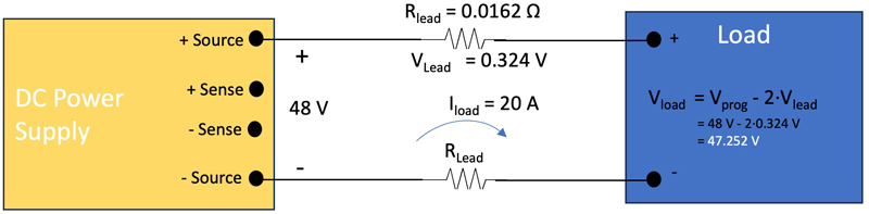
o Figure 2a shows a 2-wire configuration in which 48 V is desired at the load, but the load sees only 47.252 V due to voltage dropped across the two leads. If the power supply is acting as a charger for the load, the battery pack, the battery pack will not charge to its fully charged voltage.
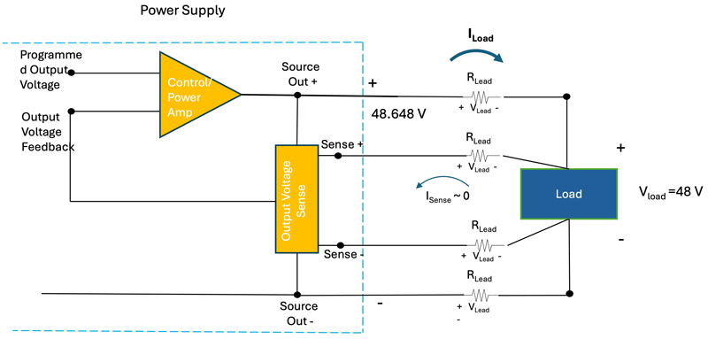
o Figure 2b shows the sensing circuit and the output stage of the power supply along with 4-wire sense wiring. A high input impedance Output Voltage Sense circuit, which draws negligible current, measures the voltage at the load. This voltage is fed back to the Control/Power Amp circuit. The Control/Power Amp circuit increases the power supply output to overcome the voltage dropped across the supply test leads. In this case, the power supply output would rise by 2 x 0.324 V or 0.648 V to 48.648 V. As a result, the voltage at the load would be the desired 48 V.
Click image to enlarge
Figure 2a: Voltage error created with 2-wire sensing
Click image to enlarge
Figure 2b: 4-wire sensing compensates for the voltage drop from the resistance of the least leads
Recommended safety tests include:
· Reverse polarity – The system needs to verify that the connections to the battery are the proper polarity. Incorrect connections can cause harmful chemical reactions and internal short circuits, resulting in the generation of excessive heat. Those conditions are the recipe for thermal runaway.
· Voltage matching – Prior to connecting the battery pack-under-test to the test system, the test system should measure the battery voltage and the voltage of the power instrumentation that will connect to the battery. A large voltage differential can result in a pulse of energy transferring from the high-voltage device to the low-voltage device. The creation of a spark is possible. The energy pulse could damage the battery pack or the test system power instrumentation. The battery cells could experience a short circuit due to breakdown in the separator material between anode and cathode. Adjusting the test system voltage to the battery pack voltage before closing the contactor connections eliminates this potential source of damage.
· Insulation resistance - Before cycling the battery pack begins, an initial test should be performed on the battery pack using a DC insulation resistance measurement. A measurement below specification can yield a potential indication of a defective battery pack due to one or more shorted cells. Removing a battery pack from the test system can avoid a potential catastrophic incident if the battery pack’s insulation resistance is below its specification.
· Pre-charging – Pre-charging a new, untested battery pack safely transitions the battery cells to their operational state. The process allows the formation of a stable electrolyte interface on the cell’s anode and stabilizes the battery chemistry. Properly pre-charged batteries have better retention of capacity. The process also contributes to balancing the cells so that all cells charge and discharge at similar rates.
· Vibration and drop testing – These two tests are quality control tests that, unlike the other tests, are recommended for testing a statistically significant quantity of battery packs in an off-line laboratory rather than on a production line. Battery packs are subject to vibration and shock during vehicle operation. Verifying that the battery packs can withstand the levels of vibration and shock in a vehicle prevents failure during operation and reduces the risk of thermal runaway due to a damaged battery.
Limits and controls that require the removal of power from the battery pack under test include:
· Overcharge voltage limit – The test system must prevent charging the battery cells beyond their maximum voltage.
· Minimum discharge voltage limit – The test system must not allow the battery cells to drain below their specified minimum discharge voltage.
· Automated shutdown – The test system should shut down in the event any battery pack parameters or internal system parameters are outside defined limit values. Software in some test systems may execute a shutdown based on algorithms that predict thermal runaway.
· Automated disconnect – Similar to automatic shutdown, connections to the battery pack-under-test should open if a limit is exceeded.
· Manual shutdown – If all else fails, an emergency stop button shuts the test system down, terminating the application of power to the battery pack.
Instrument safety features
The test system should be capable of monitoring itself. Power instrumentation needs overtemperature, overcurrent, overvoltage, and overpower monitoring to ensure safe operation. When paralleling power instrumentation to test high-power batteries, the system needs to safely control and connect the instruments. EA Elektro-Automatik (EA) power instrumentation, such as the bi-directional power supplies used in their battery test systems, has a Master-Auxiliary Bus allowing one power supply to control all other power supplies. EA also utilizes a Share-Bus connection between all power supplies to ensure that all carry an equal portion of the load and none become overloaded.
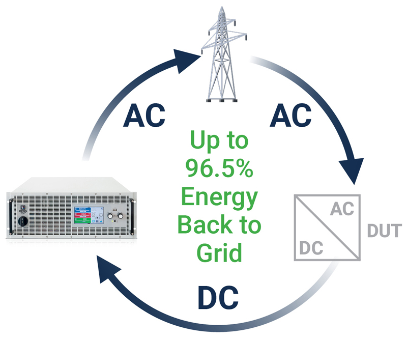
Keeping the test system within a safe operating temperature prevents damage to the instrumentation. EA battery test systems use regenerative bidirectional power supplies to charge and discharge the battery packs (figure 3). During discharge testing or cycling, the EA supplies can return absorbed energy to the AC power grid with up to 96.5% efficiency. This energy transfer from the power supplies to the AC grid saves annual utility costs and reduces the heat load on the supplies. That allows the test system to need less external cooling.
Click image to enlarge
Figure 3: The use of bidirectional power supplies reduces heat load and saves utility costs
Typically, the available space on the production floor for a battery test system is limited. A test system that consumes a minimum of floor space is desirable so that it can have adequate surrounding space for airflow to remove internally generated heat. EA can solve this problem with single test racks containing as much as 300 kW, which consume only 6.5 sq ft of floor space. A 300 kW test rack would need no more than five EA high-density bidirectional power supplies with as much power as 60 kW in a 6U high, full rack enclosure.
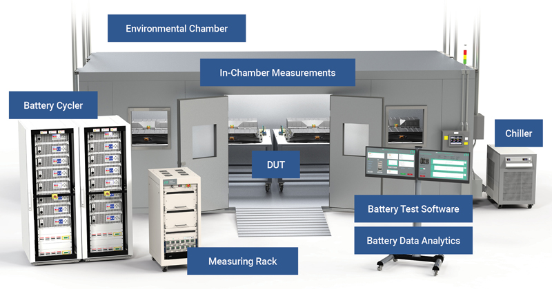
Complete EV battery test solution
A complete, safe EV battery test system should include a protected test chamber and a battery test system that monitors key battery parameters, performs important safety tests, and has appropriate limit settings. The system must also have protection for its own instrumentation. The complete solution will minimize the probability of a thermal runaway condition. Figure 4 illustrates a test system that contains all the elements for a safe EV battery test system. EA, EA-BTS 10300 Series Battery Test System, is one vendor that can provide both the design expertise and a test system solution for safe battery tests.
Click image to enlarge
Figure 4: A complete EV battery test system