Author:
Phil Goff, Flex Power Modules
Date
05/20/2024
 PDF
PDF

Click image to enlarge
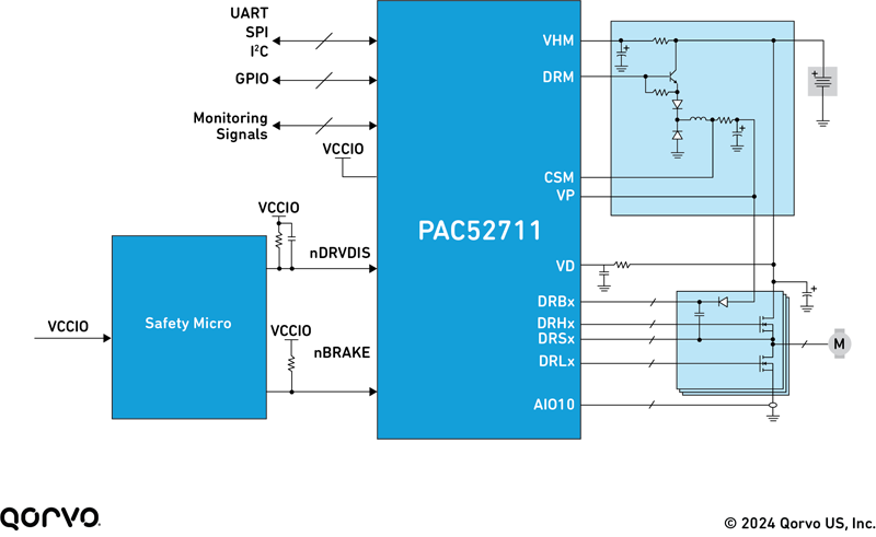
Figure 1: DC-DC converter architectures
The demand for data centers continues to grow at a remarkable pace – with AI the latest boom. While the energy efficiency of computing hardware is steadily improving, the electricity used by data centers is forecast to double by 2026. This means that there is increasing pressure on power supply systems to improve their efficiency and to reach new levels of power density.
Data center power architectures have evolved to keep up with increasing demand, and the changing needs of loads. In the past, it was practical to deploy an AC/DC converter for each rack shelf, but this required bulky, expensive wiring, and usually had overall high costs.
A newer alternative has been to use an Intermediate Bus Converter (IBC) as an extra conversion stage. In this approach, a bulk AC/DC converter is used for each cabinet, which then supplies DC power to each shelf – typically at 48V or 54V, to keep current to safe levels and to reduce ohmic (I2R) losses.
An IBC in each blade converts this 48 V supply to 12 V, and then point-of-load (PoL) converters, or more recently Voltage Regulator Module (VRM) blocks, are used to take this down to the voltages required for individual boards and chips.
In practice data centers usually run on a relatively narrow supply voltage range of 40 V to 60 V. IBCs are also suitable for use with the wider input voltage range used in the telecoms sector, which is typically 36 V to 75 V.
This IBC-based architecture has many benefits, including the potential for higher efficiency, lower wiring costs, and improved power density. However, with an extra converter stage introduced, efficiency becomes even more critical.
Why Use Unregulated IBCs?
There are three main types of IBC: unregulated, regulated, and the ‘hybrid regulated ratio’ (HRR) approach pioneered by Flex Power Modules. When choosing the best option for their specific application, a designer needs to consider multiple trade-offs including cost, efficiency, and system requirements.
Unregulated IBCs have a fixed conversion ratio, such as 4:1 (48 V to 12 V), which enables them to achieve the highest efficiency, lowest cost, and smallest size. However, their output voltage is directly proportional to the input voltage, which means the PoL converter must be able tohandle potentially large voltage variations.
Alternatively, a regulated IBC uses a feedback or feedforward loop to control its output voltage within much tighter tolerances – but this does mean the IBC will have lower efficiency than an unregulated alternative. On the other hand, keeping to a small output voltage range can significantly improve the efficiency of the PoL converter, which of course takes the IBC’s output to use as its input.
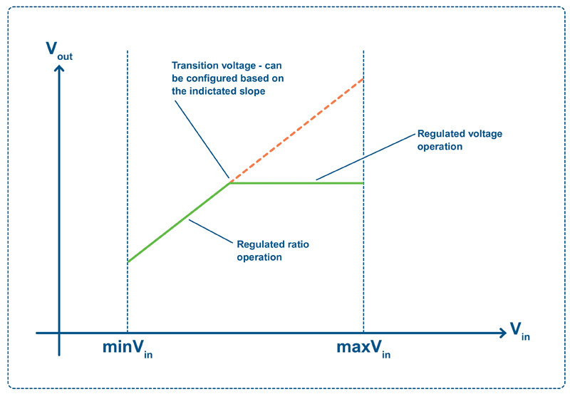
With the third option, HRR, the IBC is ratiometrically regulated up to a specific input voltage (so the output is proportional to the input), and then fully regulated above this voltage – delivering a ‘best of both worlds’ solution for many applications (see Figure 2).
Click image to enlarge
Figure 2: Hybrid regulated ratio (HRR) operation
Challenges in IBC Design
Within these different approaches, there are multiple challenges that must be overcome to achieve an efficient, reliable IBC design.
Let’s look at some of the main challenges involved in unregulated IBC design, why they are a concern, and strategies to overcome them.
Firstly, start-up can cause issues: as the duty cycle rises from zero to 100%, this can cause high ripple currents, which can overload the power stage or trigger overcurrent protection. To mitigate high ripple currents during start-up and other transitions, one approach is to control the switching frequency during the transition, which keeps the ripple current at a known level. Another option is to use a larger output inductor.
Next, synchronous rectification is an important technique in power supplies, which improves efficiency and reliability, and reduces cost. It is achieved by using MOSFETs to replace the traditional role of diodes in performing rectification.
As a MOSFET can have a smaller forward voltage drop than a diode, there are efficiency gains due to synchronous rectification. This is important in IBCs, where efficiency is vital. However, synchronous rectification does introduce some complexity in how the converters need to be driven, particularly in terms of timing.
Another challenge is to manage reverse energy flow. A MOSFET can conduct current in both forwards and backwards directions. In certain conditions, such as a sudden shutdown, a MOSFET can self-oscillate and send current backwards. To avoid this, the IBC’s control circuit can turn a MOSFET off when not needed in the cycle, which means that no energy can flow backwards.
In practice, power system design engineers may well choose to buy a complete IBC power module from their supplier. The module will have been designed to consider and mitigate all of the above challenges, and to provide the best possible performance and efficiency.
Putting it into Practice
Let’s look at some recent examples of non-isolated unregulated IBCs: the BMR313, BMR314 and BMR320 from Flex Power Modules.
For space-constrained applications, the BMR313 delivers a peak power rating of 3 kW in a tiny package, just 23.4 x 17.8 x 7.65 mm. This enables an excellent 908 W/cm3 power density with an input to output ratio of 4:1. The BMR313 leverages the advantages of the FD6000, onsemi’s latest generation, intermediate bus digital controller. At an input voltage of 54 V, the module’s efficiency is as high as 97.2% at 50% load (40 A).
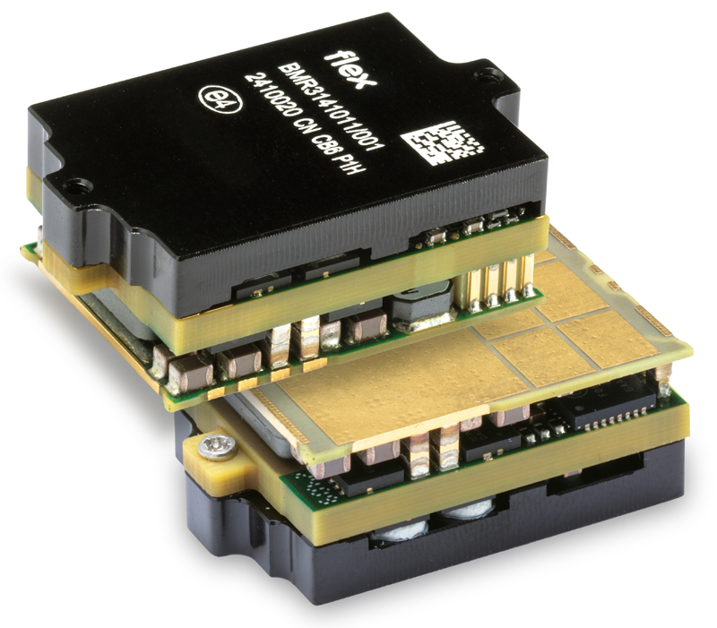
Another example of a non-isolated, unregulated 4:1 ratio IBC is the BMR314, which delivers up to 1.5 kW peak power. As with the BMR313, the BMR314 uses an industry standard LGA footprint and pin-out for security of supply and second sourcing.
Click image to enlarge
Figure 3: Flex Power Modules’ BMR314
Additionally, the BMR320 is designed for input voltages of 40 V to 60 V, and utilizes an 8:1 fixed ratio, which means that the output voltage ranges from 5 V to 7.5 V. This makes it ideal for applications that require a lower intermediate bus voltage that can be helpful to optimize overall system efficiency, when used in conjunction with downstream PoL converters, VRMs or Integrated Power Stages such as the BMR510 and others.
All three IBCs integrate a PMBus interface for ease of monitoring, configuration, and control capabilities. This also enables easy integration with the Flex Power Designer software design tool, which recently launched the latest Version 4.6. This software tool enables users to meticulously configure and optimize power systems, even without any attached hardware.
Conclusion
In summary, unregulated IBCs stand out as an optimal solution for various power conversion applications, especially within data center applications. They typically surpass regulated IBCs in efficiency and often come with a more economical design cost, making them a preferred choice for industry professionals.
Alongside the 4:1 and 8:1 input to output ratios mentioned previously, other ratios are being requested which allow system designers to optimize their overall system efficiency. Examples include 5:1, 6:1 and even 10:1, which Flex Power Modules is responding to through new product developments utilizing the latest topologies and component choices, as well as novel thermal management techniques to enable the highest power densities.
As the data center industry expands, largely fueled by the surge in AI, the demands placed on power supplies will become increasingly complex, with heightened efficiency and greater power density perpetually at the top of designers’ agendas. Faster and more powerful processors will continue to keep engineers focused on thermal management, as they try and keep cooling costs down.