Author:
Ally Winning, European Editor, PSD
Date
04/15/2025
 PDF
PDF

Ehab Tarmoom, Applications Engineering Manager, High-Power Solutions Business Unit
Safety is of critical importance in the automotive industry, and that goes just as much for EVs as it does for ICE vehicles. A catastrophic failure endangers not just the occupants of the vehicle, but everyone else on the road. As such, every vehicle is designed to be functionally safe, meaning that any situation that could pose a threat has to be investigated and measures put in place to ensure that if a failure does occur, it will always fail in a way that is as safe as possible.
In EVs, the main threats to safety are often found in the drivetrain because of its high power usage and fast moving mechanical components. The most important functional subsystems that make up the EV drivetrain are the battery, inverter and electric motor. The battery supplies power to the inverter, which energizes electromagnets on the stator of the motor in a sequence. This creates a revolving magnetic field that interacts with permanent magnets on the rotor, causing it to spin. However, if the power is cut off to the stator, then that process can occur in reverse, turning the electric motor into a generator. When this occurs, the rotor continues to spin, and its permanent magnets induce currents in the stator coils, which are fed back into the inverter. If not controlled, this current can damage the system, and even make the vehicle uncontrollable.
Ehab Tarmoom, Applications Engineering Manager of Microchip's High-Power Solutions Business Unit explains, “When a rotor shaft spins, it generates back EMF that is directly proportional to the speed of the motor. Therefore, at low speeds it'll be a low voltage, and at high speed it would be a high voltage. It is part of the normal operation of the motor, but when the power is cut off to the inverter, the rotor still turns and back EMF is generated, so the circuit’s controller has to place the motor in one of two safe states. If the back EMF is higher than the battery voltage, the motor’s windings are shorted by turning on either the upper three MOSFETs in the inverter, or the lower three. The voltages over the three phases then theoretically cancel each other out. However, in practice, losses mean that there are small voltages remaining that are easily dealt with. If the back EMF is lower than the battery voltage, then all the semiconductor switches are turned off and nothing will get rectified back into the into the high voltage system. There's no path for that current to go anywhere.”
A real problem occurs when the controller circuit also loses power and isn’t able to open or close the MOSFET switches. It is a situation that is very unlikely to ever happen, but it is not impossible, and as such, measures have to be put in place to prevent uncontrolled failure. One way to do this is to use the voltage generated by the back EMF to power the controller for the time needed to place the circuit in a safe state. This involves creating an auxiliary power supply that converts the voltage to a suitable level for the system controller. It is a process that sounds easy in theory, but because of the huge potential variance in voltage, is very difficult to achieve in practice. It was not an easy task with the older 400V EV architecture, but the newer 800V EV architecture doubles the potential input voltage range.
To assist EV manufacturers meet those requirements, Microchip has introduced an axillary power supply reference design for 800V EVs. The 45W reference design has a basic flyback converter architecture, but can accommodate a very wide input voltage range from 40V to 1000V. It has two outputs; a +22V regulated output to power the system controller and a -6V unregulated output for the system resolver.
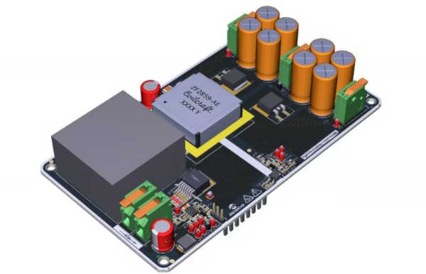
Figure 1 - 45W Auxiliary Power Supply for 800V Traction Inverters Reference Design
Tarmoom expanded by saying, “A normal flyback converter for an 800V system might have an input range from 300V or 400V up to 1000V. However, because of the functional safety aspect, the auxiliary power supply needs to be able to work down to much lower voltages. That requirement poses many challenges to providing stable control over the converter under extreme input voltage conditions and quickly changing loads. The new reference design is based around two components that are critical to meeting those needs. Firstly the transformer, developed in partnership with Coilcraft, uses current mode control with secondary side regulation to maintain a very stable output voltage. In addition, the AECQ-101 qualified, 1400V mSiC MOSFET minimizes switching losses while eliminating the need for a dedicated gate driver, enhancing system efficiency and reliability”.
All components in the circuit are automotive qualified apart from the transformer, which is currently going through the qualification process. Coilcraft is currently releasing the new transformer as a standard component. The company will also work with customers that need slightly different specifications.
Customers can download the full design, including the schematic, Gerber files and BoM to get started straight away from the link below.