Author:
Sebastian Klotzer and Ilian B from Nexperia and Maurizio Tranchero and Paolo Santero from Ideas & Motion
Date
01/20/2025
 PDF
PDF

Click image to enlarge
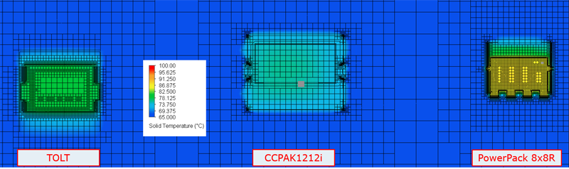
Figure 1: TOLT (a), PowerPAK 8x8R (b), and CCPAK1212i (c)
In recent years, semiconductor manufacturers have developed power component packages which use a different thermal management approach - instead of placing the thermal pad on the bottom of a device pointing towards the PCB, the exposed metal pad is placed on the top side of the device. It has been shown that top-side cooling (TSC) can reduce the overall thermal resistance by 20% - 30% compared to bottom side cooling (BSC), making the process of heat extraction much simpler and consequently less expensive to implement.
Ideas & Motion, a company which develops power inverters for electric vehicle (EV) powertrains, conducted simulations as part of the HiPE EU-funded project to assess the thermal performance of TSC packages from three leading semiconductor manufacturers. The company’s primary interest lies in exploring potential solutions and identifying the one that offers the highest thermal efficiency for their inverter designs. Thermal efficiency is a critical factor, particularly for applications such as two- or three-wheelers (e-bikes, s-Pedelecs, motorbikes, and cargo bikes), where the available space for the drive system is limited and the form factor is crucial, making high power density essential.
The TSC packages whose thermal performance is evaluated (Figure 1) include TOLT, PowerPAK 8x8LR; and CCPAK1212i (Nexperia). This article presents the methodology used as well as simulation results and conclusions.
Defining PCB Parameters
This comparison focused on evaluating package performance based on device models for a simplified but realistic thermal stack designed using Siemens’ Xpedition Enterprise software and then imported into FloTherm XT for the computation fluid dynamics (CFD) simulation.
For characterizing thermal resistance, JEDEC defines a standard 4-layer (2s2p) PCB stack-up where measurements on the device under test (DUT) must be performed in still air within a closed chamber. While this setup is ideal for characterization purposes (because it is independent of external influences), it is very different from the typical environment in which an inverter for automotive applications typically operates. For this reason, the analysis uses a stack-up typically used by Ideas & Motion in their inverter designs - 1.6 mm thick with six 70µm copper layers, which offers a decent trade-off between current capability, thermal effectiveness, and cost. The same substrate characteristics are used for each of the evaluated packages i.e. the same number of layers, copper thickness, and copper percentage.
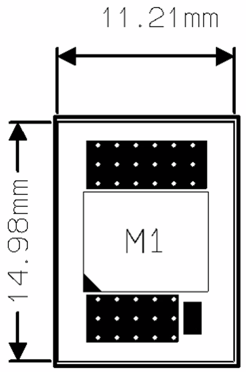
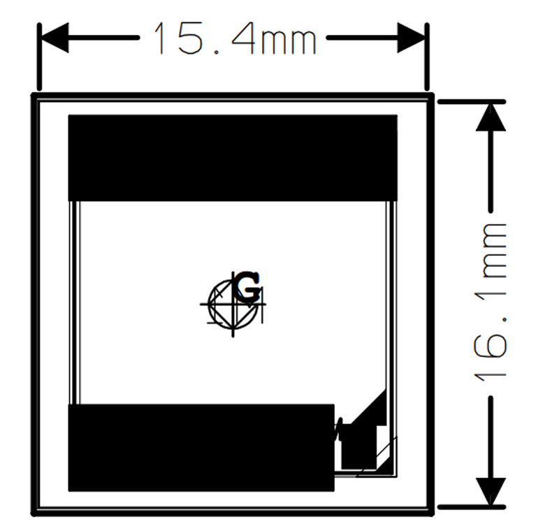
PCB dimensions are influenced by the package choice, which is typically selected for benefits in thermal resistance or size reduction. Consequently, the PCB used for testing was intentionally designed to be slightly larger than the device footprint. This approach enables the advantages of the package to be seen in a realistic use case. Drawings with explicit dimensions are shown in Figure 2, with the amount of extra area (beyond the recommended footprint) defined so as to allow heat to spread to a wider area.
Click image to enlarge
Figure 2: Footprint and PCBs for the packages being evaluated TOLT (a), PowerPAK 8x8R (b), and CCPAK1212i (c)
Thermal vias (spaced at 1.2mm) were also included to improve thermal performance at a reasonable cost. Thermal vias can be realized in many different ways, so after consulting many PCB manufacturers, it was decided that the PCB for this analysis would use only 0.4-mm filled and capped vias.
Defining Simulation Parameters
PCB definition and mechanical dimensions are not sufficient by themselves to establish the simulation environment, so the following assumptions were also made for the purposes of this analysis:
· Packages: 3D models were shared by device manufacturers and included the internal structures of the package.
· Materials: Each part of a device associated realistic materials with its properties, according to those available from the computational fluid dynamics (CFD) simulator material library.
· Thermal interface material (TIM): All devices were assumed to be in contact with a TIM 330-μm thick with a thermal conductivity of 2 W/(m∙K).
· Environment: An automotive environment was targeted with the ambient temperature set to 70° C, using the pressure value at sea level (101kPa), and a heat transfer coefficient (with air) of 10 W/(m²∙K)
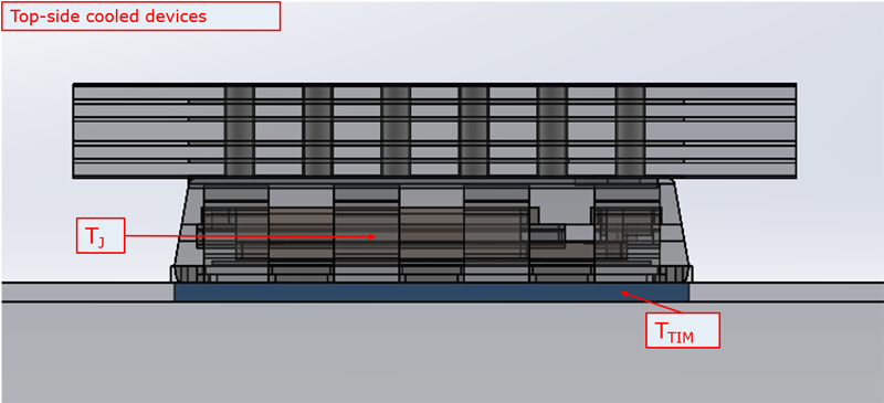
· Stimulus: Each device dissipated the same power compatible with continuous (3 W) and peak (10 W) conditions (note that this power level is lower than that typically dissipated by a device in a practical application but was selected as a convenient reference figure for comparative purposes). To compare the thermal performance of these packages, an equivalent thermal resistance was defined as the difference between the hot-spot (i.e., the junction) and the surface of the TIM as shown in Figure 3.
Click image to enlarge
Simulation Results
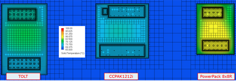
Figures 4 and 5 use a colored scale between 65° C (slightly below ambient temperature) and 125° C to graphically illustrate the simulated heat dissipated in each package and its TIM respectively. Nexperia’s CCPAK1212i is clearly the coolest device, a result which at first glance might simply be explained by its larger size (and hence bigger pad area allowing greater power dissipation towards the heatsink). This correlates with Table 1 which contains the simulated thermal resistances for each package and shows the CCPAK1212i to also have the lowest thermal resistance.
Click image to enlarge
Click image to enlarge
However, to gain better insight into the effectiveness of each package, it is possible to define surface power density (SPD) with respect to the whole device footprint or only to the power pad. These metrics, which have different purposes are defined as follows:
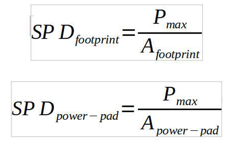
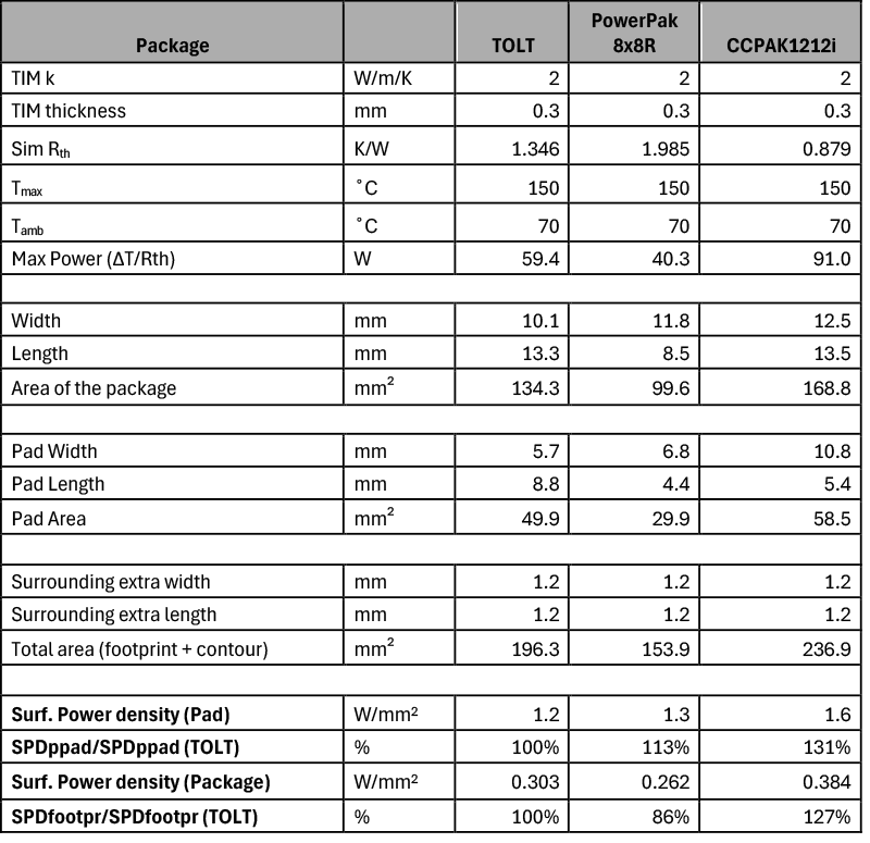
SPDfootprint compares the effectiveness of a given solution to produce compact power converters, since it expresses how much power can be handled by the power electronics components in an end application. SPDpower-pad provides a way to evaluate the technology used to transfer heat away from the chip by comparing the heat transfer of a package with respect to a given thermal interface area. By examining SPDpower-pad in Table 1, it is clear that the TOLT package (which is based on older wire-bond technology) has lower thermal capability compared to the PowerPak 8x8R and CCPAK1212i packages, which both use copper clip technology. On the other hand, the PowerPak 8x8R is the worst performer for SPDfootprint, showing the difficulty in removing heat internally generated within a smaller footprint package. Based on this metric alone, the other two packages are more suitable for high power densities, thanks to their larger power pads. However, it is notable that SPDpower-pad of the CCPAK1212i outperforms the two other packages by up to 31% and its SPDfootprint is also up to 27% better. Taking both of these metrics together, it is clear that CCPAK1212i offers the overall best thermal management solution.
Click image to enlarge
Conclusion
It is overly simplistic to assume that the thermal performance for TSC packages largely relates to the physical dimensions of their exposed pad. Simulations have shown that for a practical EV inverter application, Nexperia’s CCPAK1212i TSC package is the best choice because it offers the lowest thermal resistance with respect to surface power density when compared to competing TSC devices with a similar sized footprint.