There is always a demand for more safety and service continuity in critical systems for many applications, including industrial drives
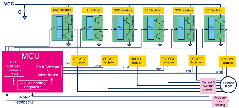
Figure 1: Block diagram of a Modular six-phase Fault Tolerant drive
Safety and reliability can be achieved if the electrical drive can identify and manage the fault, in the fastest way possible, ensuring the safe operations. Multiphase motor drives, like the system described in this article, can sustain multiple fault events maintaining performance comparable with normal conditions.
This article details a proposed modular and flexible fault-tolerant architecture, powered by a high-performance microcontroller and robust power switches It will explain smarter use of the hardware, including how to implement effective redundancy compared to systems of the same power level.
There could be some concern raised regarding the higher number of devices in the multiphase drive compared to standard three-phase inverters. Clearly for low/medium-current systems, a higher number of devices represents extra “cost”, but for higher-current systems the power transistors parallelization is a common procedure, offering several benefits such as the cost reduction of optimizing packages, connectors, conductors, and improved thermal dissipation. Using parallel connected power transistors in a three-phase inverter brings the total number of electronic switches to twelve, the same number as the presented six-phase solution; but with the advantage of having greater degrees of freedom, which allows a rotating magnetic field to be produced, even in the presence of faults.
The following parts of this article are describe the three key aspects of the fault tolerant system: detection and identification, segmentation and compensation of the fault conditions.
Fault Detection and Identification
The most common faults occurring in the electro-mechanic system, comprising the voltage source inverter (VSI) and the electrical motor, are power transistor faults and motor phases faults.
Power transistor faults can be classified short-circuits or open-circuits. Equivalently, the faults in the motor windings can be classified as open-phase fault or short-circuited-phase fault. The first, and more challenging, task of a fault tolerant system is to manage both the short-circuit and the open-circuit faults in the inverter. To do this, short circuit faults must be converted to open-circuit faults using a proper fault isolation system to allow execution of the fault compensation control logic. This will guarantee continuity of service and optimize performances during faulty operation. Depending on how critical the system is, some fault events can be left out of the fault-tolerant solution, and then only safety can be guaranteed.
Figure 1 shows a block diagram of a modular six-phase fault-tolerant drive able to support the following kind of faults:
· Short Circuit Faults (SCF)
o Inverter leg short-circuit (DC-Link fault)
o High or low-side device SCF
· Open Circuit Faults (OCF)
o One or both inverter leg power switches (e.g. gate drive circuit fault)
o Motor winding open phase
Other kind of faults aren’t covered by this article and will be subject of further studies.
The short-circuit faults (SCF) are the most critical among the considered faults, mainly due to the high level of energy that is produced which can cause component explosions, flames and/or spark generation. The system is usually protected using proper protection components that disconnect the damaged system from the power source after a set time; unfortunately, this guarantees only safety and not service continuity since the entire converter is then isolated.
The advantage of the proposed solution is having a higher degree of freedom in comparison to a conventional three-phase drive, which can be integrated by designing a proper SCF isolation circuit, that is able to isolate only the faulty part (e.g. inverter leg).
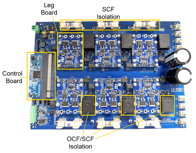
Figure 2 shows the implemented modular six-phase evaluation drive that embraces the idea of replacing only the damaged parts, making the system more sustainable. Additionally, this allows for the separation of PCB tracks that are sensitive to short-circuit faults, limiting the possibility of damaging the common circuit and rendering the fault-tolerant design ineffective. It is composed of six modules (leg boards) hosting the STGAP2D half-bridge isolated gate driver and two trench gate field-stop, 650V, 20A, M series low-loss IGBT (STGB20M65DF2). The main board hosts six fast acting fuses as the SCF isolation system and six normally closed relays mounted at the inverter output to disconnect the motor terminal from the inverter leg (OCF/SCF). The finished evaluation system is a power scaled demonstrator used to evaluate the system architecture and control strategy.
Fault detection and identification are managed by a STM32 microcontroller implementing a patent pending algorithm, which is also able to detect the faulty half bridge legs of the inverter.
Fault Isolation
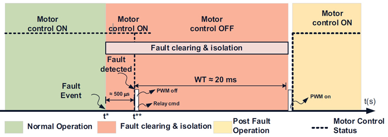
The worst failure scenario is the short circuit of one entire inverter half bridge. This condition requires fast action from the SCF isolation system. This is achieved using the six fast acting fuses which, with a properly sized bulk capacitor, isolate the faulty leg from the DC positive terminal. These fuses also limit the energy flowing in the short-circuited power switches, avoiding disruption of the package and spark generation.
The effectiveness of fault isolation is reached by opening the related phase relay and disconnecting the motor terminal from the damaged leg.
This last action necessary is to allow independent control of the current flowing on the remaining motor phases after the fault event. The relays opening commands are generated by the fault detection and identification algorithm and sent through the MCU digital output ports. The PWM is disabled during this so called “waiting time” (lasting 20-25ms). During this time the motor windings will disperse the accumulated magnetic energy, while the relay is open with low or zero current. This avoids overvoltage on the terminals that can further damage the relay itself.
Fault Compensation Control Strategy
Even if a multiphase motor is intrinsically fault-tolerant, its performance can be further improved by developing proper fault compensation control. This is achieved by applying optimization criterion according to the application and operating point. The described fault detection and identification algorithms and the fault compensation strategy are managed by the same MCU. In Figure 2 the control board embedded in the system is based on a STM32G473QB microcontroller operating at 170 MHz and featuring 128 Kbyte of Flash memory, math accelerator, and a single-precision floating point unit (FPU), which is used by the multiphase Field Oriented Control (FOC) system and by the fault management algorithms (detection, identification, and compensation).
The fault compensation algorithm applies a specific phase currents sequence, in terms of amplitudes and angle displacement, aiming to generate a sinusoidal electromagnetic field even during faulty conditions (one or more motor phases are not available). This allows the mitigation of torque ripple due to low harmonic content of phase currents, and to produce the same torque as normal conditions (if possible, considering the overload limitation of the motor and electronic devices).
Click image to enlarge
Figure 2: STEVAL-FTD01KCB
Figure 3 highlights the time sequence from the fault event to motor drive reconfiguration, passing through fault detection, identification, and isolation.
Click image to enlarge
Figure 3 : Short Circuit Fault timing diagram
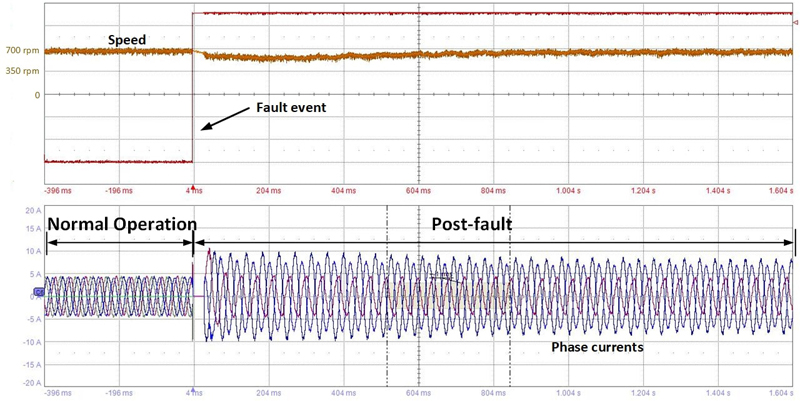
Figure 4 shows the experimental results obtained during a stress test of the system under a triple short circuit fault (the worst case sustainable) during normal operation. Before the fault occurs, the 6-phases induction motor runs at 700 rpm, with 5Nm of mechanical load. It can be seen before the fault, the currents distribution and amplitude are symmetrical. In the post-fault condition, the currents are asymmetrically distributed and have different amplitudes. The choice of amplitude and phase displacement is calculated according to the fault combination to guarantees the sinusoidal waveform of the electromagnetic field and the same torque of the pre-fault condition.
Click image to enlarge
Figure 4: Triple fault occurred during normal operation (700 rpm, 5Nm)
Conclusions
The tests done on the evaluation system confirm the effectiveness of the Fault Tolerant Multiphase Inverter (FTMI) in handling very stressful fault conditions, such as inverter leg short circuits, allowing the isolation of the damaged inverter part and effective recovery of current control. This proof of concept and the acquired knowledge can be used as base to design a higher power system and to adapt the control technique to other types of electrical motors and applications.
 - small.jpg)