Author:
Ally Winning, European Editor, PSD
Date
10/01/2024
 PDF
PDF

Frederik Dostal, Subject Matter Expert for Power Management, Analog Devices
Multiple power rails are now a fact of life for power designers. Whether it is to supply power at board level or to an individual IC, it is likely that two or more different voltage levels will be required for the circuit to operate correctly. Designers often use their own experience and instinct to decide how the power architecture in these designs should look, but that may not provide the optimal result for their own application. There are lots of good tools available to help engineers plot out designs, but the most commonly used tools, such as CAD and simulation packages, often require the main decisions to be made before use. It is possible to use them for ‘what if’ scenarios, but that tends to be very time consuming.
Analog Devices has incorporated a tool in the company’s LTpowerCAD software package that allows engineers to quickly test different multi-rail scenarios, and make decisions on the best system power-tree diagram for their particular application before committing to the architecture. Currently, LTpowerPlanner is one of the least used of the tools included in the software package, but Frederik Dostal, Subject Matter Expert for Power Management at Analog Devices believes that with multiple voltage designs becoming more prevalent, and also increasing in complexity, engineers are missing a trick by not using the tool to take a lot of the guess work out of the design process.
He explains, “Some very important traits of multi-rail system are defined in the architecture, including total efficiency, solution size and cost. If an engineer selects a number of DC/DC converters to do the job and puts them on the board, there's the risk that the overall architecture will not be optimized. It makes sense to have a system level planning tool that helps to lay out the architecture, and also calculates the total power, input power, output power, efficiency, and solution size. LTpowerPlanner is completely free, easy to use, and it allows engineers to quickly see the different options available to them.”
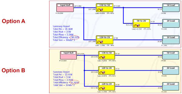
Figure 1; Two alternative architectures for the same system generated in LTpowerPlanner. While option B has the higher efficiency, there could be genuine reasons for choosing option A for the final design. Option B may turn out to be larger, more expensive, or the shorter duty cycle may not be appropriate for the application.
LTpowerPlanner is easy to use, but also has some powerful features. Initially, the designer inserts the input voltage, and blocks representing the load, which can be individually defined with voltage and current requirements. Then DC/DC converter blocks are added along with any LDOs. The blocks are ‘wired’ together to complete the architecture. The DC/DC converter blocks can then be defined by efficiency figures from data sheets. The details of any available DC/DC converter can be used.
The tool calculates the total efficiency of the architecture based on individual currents and voltages of each block. A summary report is generated with the total input power, total output power, the total efficiency of the whole power tree. It also feature options that can make the calculations much more accurate, both for size and efficiency. Device sizes can be included, and additional components such as filters, passives and fuses that affect the overall system efficiency can also be added and defined. Real-world examples of circuits are also included, both to demonstrate the tool and to provide a basis for more complex designs.
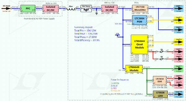
Figure 2; Examples like this datacom system power tree are included in LTpowerPlanner for modification.
Once the architecture has been defined in LTpowerPlanner, it can be easily imported to LTpowerCAD for refinement or LTspice for simulation.